Showing posts with label Ring spinning. Show all posts

Twin Air-jet Nozzle System for Ring Spinning

Design and Development of Twin Air-jet Nozzle System for Ring Spinning

The utility of the air-jet and ring combination has been known in the last decade, on its ability to reduce the yarn hairiness. However, it still offers enough scope for further work, with respect to its application in cotton spinning. In the recent past, it has been proved by the textile researchers that with the employment ofair -jet nozzle in ring spinning the yarn hairiness could be reduced. This paper examines the effect of employing twin air-jet nozzle in ring spinning. In this study an attempt has been made to combine the advantage ofair -jet spinning system, with conventional ring spinning system.

Two types of air -jet nozzle similar in all dimensions but differing in the direction of inclination of orifice, namely, ‘S’ nozzle and ‘Z’ nozzle and a suitable air chamber to house these two nozzles in tandem have been designed and fabricated. This twin air-jet nozzle assembly has been positioned in between the front roller nip and lappet hook without altering the spinning angle. The yarn emerging from the front roller nip has been guided to pass through the twin air-jet nozzle and subjected to the action ofopposing swirling air current created by air vortex inside the nozzles. Trials have been conducted in mill condition on 30's carded count on conventional ring spinning machine without and with twin air-jet nozzle under four different combinations of air pressure, ie, 0.25/0.25 bar, 0.25/0.50 bar, 0.50 /0.50 bar and 0.5/1.0 bar in the ‘S’ and ‘Z’ nozzles, respectively.

The yarn samples thus produced have been tested for their properties like tenacity, elongation, evenness, imperfections, hairiness, diameter and twist. From the results it has been observed that the introduction of twin air-jet nozzle system in ring spinning has lead to better compaction of yarn with improvement in yarn quality index, yarn tenacity and packing factor. The twin air-jet nozzle system under 0.25 / 0.50 bar pressure combination in the ‘S’ and ‘Z’ nozzles has produced the best results with 17.5% increased tenacity, 18.8 % improvement in Yarn Quality Index and 15% increased Packing Factor, when compared to regular ring spun yarn. This paper proves that the twin air-jet nozzle technology could be beneficially employed for the improvement of yarn quality by the spinning industry.

Keywords: Ring spinning; Yarn hairiness; Twin air-jet nozzle system

INTRODUCTION

The ability of the spinner to keep the hairiness down and in turn reduce the number of imperfections during winding is gaining much importance in this era of stringent quality norms1,2. The fibres can be made to bind into the yarn structure by the use of methods like compact spinning where the spinning triangle is reduced or by the means of some external element like a pressure column or an air-jet nozzle that reduces the yarn hairiness. Research work on hairiness reduction using such methods has been going on for some time now. Kalyanaraman’s3 study shows that the hairiness in cotton yarn can be reduced by the use of a pressure column in between the lappet hook and front roller nip. Wang, et al4 studied the application of an air-jet nozzle in between the front roller nip and the lappet hook. They proved that there was considerable reduction in the hairiness index. This was explained by the tucking of fibres due to the swirling air current which resulted in loosening and tightening of the yarn structure. Ramachandralus has studied the influence of the air-jet nozzle

on the various ring yarn properties. Ramachandralus carried out research work using both ‘Z’ and ‘S’ type of nozzles and found that the Z nozzle performs better by producing yarns having higher tenacity and lower hairiness index of the yarn when subjected to the action of air vortex.

In this paper the application of both the type of nozzles fitted in tandem between the roller nip and lappet hook of ring frame is studied. This paper examines the effect of different combi­nations of pressures of air administered inside both the nozzles on the yarn quality aspects such as tensile properties, hairiness and packing factor.

This research work aims at

· design and development of twin air-jet nozzle system for ring spinning; and

· evaluating the influence of the twin air-jet nozzle on the quality of ring spun yarn under different air pressure combinations in the two nozzles.

RESEARCH METHODOLOGY

A cotton roving of 0.91 hank was produced in the usual manner and 30 s K yarn was produced with the following process parameters.

clip_image002

clip_image004

Design and Fabrication of the Twin Air-jet Nozzle

The material used for the manufacture of the nozzles was Brass. Two nozzles with the same dimensions but differing in the direction of the orifices were designed and fabricated. One nozzle was designed to produce air vortex with rotational direction opposite to that of mechanical twist ( S nozzle ) while the other was designed to produce air vortex with rotational direction same as that of mechanical twist ( Z nozzle ).

The two nozzles were housed in air jacket in tandem and this assembly was mounted in between the roller nip and the lappet hook in ring frame in a similar fashion like the N1 and N2 nozzles of air-jet spinning. Compressed air was administered inside both the nozzles through the air jackets and yarn samples were produced under four different air pressure combinations in ‘S’ and ‘Z’ nozzles as given in Table 1.

The yarn samples thus produced with and without the twin air-jet nozzle arrangement were tested for tenacity, elongation, evenness, imperfections, hairiness, diameter and twist.

RESULTS AND DISCUSSIONS

The results obtained in the present study on various properties of ring spun yarn with and without twin air-jet nozzle system are tabulated and analysed.

clip_image006

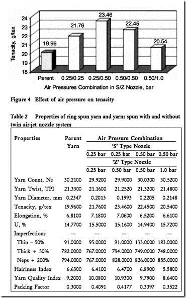
The physical properties of yarn, such as, count, twist, tenacity, elongation, unevenness, imperfections, hairiness, yarn dia­meter and yarn quality index of all the samples produced with and without using twin air-jet nozzle are shown in Table 2 and the comparison of results are depicted in the form of histograms in Figures 4-7.

It is observed from Table 2 that the employment of twin air-jet nozzle system contributes to the improvement of certain yarn quality parameters, such as, Tenacity and Yarn Quality Index. It could be noted that the system doesn't affect other quality aspects, such as, elongation and imperfections in general.

clip_image008

clip_image010

clip_image012

clip_image014

Effect of Twin Air-jet Nozzle System on Tensile Properties

It could be observed from Table 2 that except 0.50 bar-1.0 bar pressure combination in the ‘S’ and ‘Z’ nozzles, all other air pressure combinations have resulted in increased tenacity when compared to the parent yarn which was spun without twin air-jet nozzle arrangement. The percentage increase in tenacity over parent yarn pertaining to different air pressure combinations are shown in Table 3.

The increase in tenacity of yarn spun with twin air-jet nozzle could be explained as follows:

When the fibre strand leaves the front roller it is encountered with the action of the air vortex inside the ‘S’ nozzle. This air vortex, which is rotating in the direction opposite to that of the yarn twist, ie, ‘S’ direction and moving in the direction opposite to that of yarn flow will detwist the yarn and loosens its structure. When the yarn comes out of the ‘S’ nozzle and enters into the Z nozzle, it encounters with the air vortex which is rotating in the direction same as that of the yarn twist, ie, ‘Z’

direction, and moving in the direction opposite to that of yarn flow. Here, the loosened structure of the yarn undergoes re-twisting in the ‘Z’ direction and gets tightened. When the yarn comes out from the ‘Z’ nozzle it is further twisted and tightened by the mechanical twist inserted by the revolution of the traveller. This loosening and tightening up of the yarn structure results in the compaction of yarn, which is believed to contribute to increase in yarn strength.

It could be seen from Table 2 and Figure 4 that the air pressure combination of 0.25 bar-0.50 bar has produced the best result in tenacity showing 17.54% increase and 0.50 bar-1.0 bar combination has produced yarn with the lowest improvement in tenacity, ie, 2.91%. Hence, it could be taken that with the given nozzle design, 0.25 bar-0.50 bar combination is the most suitable one.

Regarding elongation it could be observed from Table 2 that the twin air-jet nozzle system doesn’t affect that property which is evident from the fact that the elongation percentage obtained at various air pressure combinations do not differ much with that of parent yarn spun without twin air-jet nozzle arrangement.

Effect of Twin Air-jet Nozzle System on Evenness

From Table 2 it could be seen that the twin air-jet nozzle system doesn’t seem to affect the evenness of yarn, as there is not much difference in the value of U% obtained for yarns spun under different air pressure combinations when compared to the parent yarn.

Effect of Twin Air-jet Nozzle System on Imperfections of Yarn

From Table 2 it could be noticed that there is not much difference in the values of various imperfections obtained for the yarns spun with different air pressure combinations when compared to the parent yarn.

Effect of Twin Air-jet Nozzle System on Yarn Quality Index

From Table 2 it could be observed that except 0.50 bar-1.0 bar air pressure combination, other combinations of air pressure have produced yarns with better YQI values. The percentage increase/decrease in YQI when compared with the parent yarn is given in Table 4 and Figure 5.

From Table 4 and Figure 5 it is evident that 0.25 bar- 0.50 bar air pressure combination has registered the highest YQI showing 18.8% increase over the parent yarn. This is due to the higher tenacity value obtained in case of 0.25 bar- 0.5% bar combination.

clip_image016

clip_image018

clip_image020

Effect of Twin Air-jet Nozzle System on Hairiness of Yarn

From Table 2 and Figure 6 it could be observed that 0.50 bar-1.0 bar pressure combination works well as far as hairiness reduction is concerned. It has accounted for in 15.8% reduction in hairiness. This could be due to the sweeping and binding action of the air vortex at 1 bar air pressure in the ‘Z’ nozzle as explained by Ramachandralu5. But under other air pressure combinations there is not much difference in hairiness values when compared to parent yarn.

Effect of Twin Air-jet Nozzle System on Compaction of Yarn

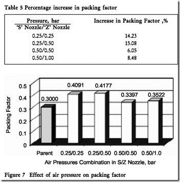
From Table 2 and Figure 7 it could be observed that the twin air-jet nozzle system results in producing yarns with reduced diameter which helps essentially in increasing the packing factor. The percentage increase in yarn packing factor obtained under different air pressure combinations is shown in Table 5 .

It could be observed from Table 5 that all the air pressure combinations have produced yarns with improved packing factor, which is a clear indication that the yarn undergoes compaction with twin air-jet nozzle arrangement.

It could be also observed from Table 5 that 0.25 bar- 0.50 bar combination has condensed the yarn to the maximum extent with 15.07% increase in packing factor.

With these values it could be confirmed that the compaction of the yarn samples produced with twin air-jet nozzle system has contributed to the increase in the tenacity of yarn as discussed earlier in this paper. This corroborates well with the findings of Ramachandralu5.

Effect of Twin Air-jet Nozzle System on Yarn Twist

From Table 2 it could be noticed that there is not much difference in the values of TPI obtained for the yarn spun with different air pressure combinations when compared to the parent yarn. Hence, it could be taken that the twin air-jet nozzle system does not affect the TPI of the yarn.

CONCLUSION

l In general twin air-jet nozzle arrangement is found to contribute to the improvement of Tenacity and Yarn Quality Index under different pressure combinations of air administered in the ‘S’ and ‘Z’ nozzles.

l In general it is found that the structure of yarn undergoes compaction exhibiting increase in Tenacity and Packing Factor with the twin air-jet nozzle system.

l In particular the twin air-jet nozzle arrangement is found to produce the best results with 0.25 bar-0.50 bar air pressure combination in ‘S’ and ‘Z’ nozzles showing 17.5% increase in yarn Tenacity and 18.75% improvement in Yarn Quality Index.

clip_image022

• In particular the air pressure combination of 0.25 bar­0.50 bar in ‘S’ and ‘Z’ nozzles is found to condense the yarn to the maximum extent with 15% increase in Packing Factor.

ACKNOWLEDGEMENT

The authors thank the Management, Principal and Head of the Department of Textile Technology, PSG College of Technology for providing the facilities to carry out the research and the encouragement extended during the course of the research work.

The authors are grateful to the Management of The Lakshmi Mills Co Ltd for permitting to carry out the trials at their Palladam Unit and the Vice President Technical, General Manager and the Technical Officers for their technical and logistic support without which this research work would have been not completed successfully.

The authors thank Dr V Subramanian, Chair Professor Anna University, for the useful discussion on this study.


Prof K Ramachandralu, Non-member V Ramesh, Non-member

Read more...

How to process cotton/long staple fibre blends on short staple ring frame

An attempt has been made to blend cotton fibres with long staple fibre strands made of silk and polyester-wool using siro spinning system and to evaluate the samples produced for some physical properties. Blending of these fibres using siro spinning appears to be possible at low spindle speeds. Yarns produced in the modified drafting system show better moisture content, evenness and hairiness, and these properties are influenced by the cotton fibre content in the blended yarn.

Keywords: Hairiness, Index of irregularity, Moisture content, Poly-wool, Silk, Siro-spun yarn, Tenacity

1 Introduction

In siro spinning, two similar or different roving strands are fed into the drafting zone and maintained separately throughout the drafting process till the nip of the front roller, using suitable guides in the middle zone and also prior to delivery rollers. At the nip of the delivery roller, both the strands are condensed, twisted together and wound by the spindle. Convergence of strands at the delivery roller is governed by spinning speed, strand twists and fineness of the yarn; optimal convergence angle of the two strands in equilibrium is 90° with resonance at 127° (refs 1,2) Many attempts have been made earlier to process worsted roving materials on the cotton ring spinning system with suitable modifications in the drafting system, though the longer wool fibres are stretch-broken.3'4 Also, extensive works have been carried out in the siro spinning using short staple spinning system, nevertheless the literatures related to siro spinning of cotton and long staple fibres are not available. Effects of strand spacing, apron spacing, yarn twist, spindle speed and break draft on yarn tenacity, elongation, evenness, hairiness have been studied earlier using cotton527, viscose", acrylic 1°, polyester-cotton11, polyester-viscose'', jute-cotton12 blends in short staple spinning systems. Attempts have also been made to produce polyester-wool blends13 with the optimized strand spacing in the drafting zones in the short staple fibre ring frame. In the present work, an attempt has been made to produce cotton/polyester-wool and cotton/silk blended yarns through short staple spinning process by modifying drafting zone of the short staple spinning system.

2 Materials and Methods

2.1 Materials

Cotton fibres (MCU-5) with 1.46 dtex (3.7 lg/inch) fineness, 29.4 mm span length (2.5%) and 13.9 mm span length (50%) were used to produce cotton roving with 0.369 ktex linear density through short staple spinning preparatory machines (M/s Ramakrishna Spinning Mills, Coimbatore). Silk roving was produced from mulberry silk with a linear density of 0.492 ktex (1.3 dtex per fibre, 94mm average length and CV% 23) through long staple spinning preparatory system (M/s Himatsinghka Filati, Bangalore). Long staple polyester-wool (75:25) blended roving with a linear density of 0.295 ktex was produced using the variable cut length polyester fibres (2.2 dtex) with a mean fibre length of 72 mm (CV% 4.2%) blended with merino wool of 22.5 micron diameter and Hauter average length of 75 mm (CV% 35%). The wool was procured from M/s Raymond India Limited, Vapi. Both silk and polyester-wool (here after poly-wool) blends were processed on NSC FM7N rubbing frame with 5 rubs/m.

2.2 Methods 2.2.1 Spinning

Double rove spinning of cotton/silk and cotton/poly-wool roving materials was carried out in

clip_image002

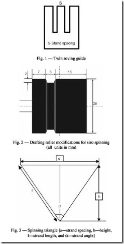
the short staple ring frame (LR G5/1 with P 3-1 drafting system) with the total draft of 28.8 (break draft 1.28) to produce the nominal resultant count of 35 tex and 25 tex respectively with a metric twist multiplier of 120. The distance between two roving strands was maintained at 6 mm using a specially fabricated guide at the back, middle zones ( Fig. 1) and grooves were made in the middle apron top roller in the drafting system to replicate the slip draft system

adopted in long staple spinning systems 14 ( Fig. 2).

Cotton roving strand was made to pass through normal portion in the same roller, for drafting separately and throughout processing, the spindle speed was kept constant at 8000 rpm.

2.2.2 Angle of Spinning Triangle

The angle of the spinning triangle was calculated theoretically using the strand spacing and height of the triangle measured during the processing (Fig. 3), as reported in the literatures!' 15 Roving strands of long staple fibres were used for the calculation of angle of spinning triangle, using a double grooved top roller (not shown here as it is not used for other purposes).

2.2.3 Linear Density

An automatic wrap reel with a perimeter of 1.5 yards was used to prepare the leas having a length of 120 yards. The skeins were conditioned and weighed for the calculation of linear density as per ASTM D1907-01 test method. Average of 20 measurements was taken for the calculation of linear density and coefficient of variation.

2.2.4 Unevenness

Unevenness of the yarns was measured as suggested in ASTM D1425-96 procedure using capacitance based Uster unevenness tester UT3. Spectrograms were obtained to assess the periodic faults and to take the remedial actions. Index of irregularity was calculated using the following formula:

Index of irregularity = U % Actual/U % Limit

2.2.5 Hairiness

Hairiness count and average hairiness values were calculated as stated in ASTM D5647-01 using photo­electric based testing system attached with the Zweigle G566 hairiness tester with a pretension of 5 cN. The test length of 100 m from each specimen was tested for the fibres having a length of 3mm at the speed of 50 m/min. An average of 5 readings was taken for the purpose. The instrument also gives the total number of protruding fibres having a length above 3mm (S3) and its variation over the mean value.

2.2.6 Moisture Content

Specimens were weighed and conditioned at 23°C±2°C temperature and 65±2% relative humidity to reach the equilibrium conditions. The tests were

carried out using ISO 1833-1980 test method, Carbolite oven and Metier weighing balance system. The difference between the initial and the final weights was expressed as moisture content of the specimen.

2.2.7 Tensile Properties

Tensile properties were measured using Premier Tensomaxx 7000 tensile testing equipment and experiment was carried out as per ASTM D2256-02. Specimens with a length of 500mm at a strain rate of 250 mm/min were used to obtain the values of breaking tenacity and breaking elongation. For every sample, 200 tests were carried out. Mean values and coefficient of variation were taken for the report and analysis.

3 Results and Discussion

No observable end breaks while spinning have been recorded, though the spinning triangle formation at the delivery is not stable due to difference in the linear densities of roving materials used in the experiments. The increase in hairiness is observed in the delivered yarn, visibly, in the absence of twin roving guides in the drafting zone.

3.1 Unevenness

Twin roving condensers placed in the drafting zone facilitate the movement of roving strands in stable conditions, and in the absence of condensers the roving strands become dynamically unstable, as shown by higher horizontal vibrations at the delivery of strands. The angle of spinning triangle increases with the increase in strand spacing, but decreases at higher strand spacing (Fig. 4). A negative correlation with a coefficient of —0.967 is observed between height of the triangle and spinning angle. The linear density of the yarns produced through the double rove spinning shows the variation (Table 1) that is within the preferred tolerance levels.16

Lower unevenness values are observed in the case of silk yarns followed by cotton and poly-wool yarns. In the case of cotton blended yarns, unevenness values are found to be higher in the cotton/ poly-wool yarns than in cotton/silk blended yarns (Table 1). Very high values obtained in the case of poly-wool and cotton/poly-wool yarns could possibly be due to the lower number of fibres in the yarn cross-section, which also shows a perfect negative correlation (coefficient —0.995) with U%. Also, lower number of fibres in the yarn cross-section results in higher limiting irregularity and index of irregularity in these yarns, as compared to the silk and cotton/silk blended yarns, which could be an important parameter in this case rather than the linear density and its effect. Interestingly, even with more number of fibres in yarn cross-section, the observed unevenness values are found to be higher in the 100% cotton spun yarn, possibly due to the slip draft arrangement and wider

clip_image004

clip_image006

draft zone setting, originally set for processing long staple strands. Total imperfections, as calculated by the sum of thin places, thick places and neps, are found to be very less in the case of 100% silk (62) and cotton/silk (93) spun yarns, while high values are observed in the case of poly-wool and cotton/poly­wool spun yarns, i.e. 230 and 265 respectively.

3.2 Hairiness

Hairiness values measured in the yarn indicate the amount of short fibres and the variations in the fibre lengths, since the majority of the protruding hairs is contributed by the short fibres. Lower hairiness values are observed in the case of poly-wool spun yarn followed by silk yarn as compared to that in the case of cotton yarns (Table 1). The highest hairiness value observed for cotton could possibly be due to the wider roller setting and slip draft arrangement used in the process, which are not normally used in such systems. Marginally higher hairiness values are observed in the case of cotton/silk yarns followed by cotton/poly­wool yarns, which demonstrate the influencing role of the cotton fibres. Larger difference is found in mean fibre lengths of silk and cotton fibres as compared to that in poly-wool and cotton fibres. Lower values observed in the case of blended yarns could be, as stated in the literature, due to the trapping of the surface fibres in the individual strands, prior to the formation of the twisted strands!'"

The S3 value is found to be very high in the case of 100% cotton yarn (S3 = 1007) compared to that in case of silk (539) and poly-wool (318) yarns. Cotton / silk (S3 = 960) and cotton/poly-wool (S3 = 959) blended yarns show marginal decrease in the S3 values as compared to cotton yarn, though the values are higher than that found without cotton content.

3.3 Moisture Absorption

The moisture content values of the conditioned samples are found to be lower in the case of cotton and poly-wool yarns and higher in the case of silk yarn (Table 1) and therefore the cotton / silk yarn shows higher moisture content than the cotton / poly-wool yarn. The value for poly-wool yarn is found to be lesser than that of silk yarn in spite of higher regain value of wool fibres, mainly due to higher proportion of polyester in the blend.

3.4 Tenacity and Elongation

The shape of the force-elongation curves shows distinct features, clearly dominated by the presence of different component fibres. Tensile properties of the blended yarns have been dealt elaborately in the past by many authors in terms of component fibres present in the yarn structure!' In the case of cotton spun yarn, no clear yield point is visible in all the tests while it is observed in the cases of silk and poly-wool yarns. However, the yield point is unidentifiable in the case of cotton/poly-wool blended yarn, though both polyester and wool fibres can exhibit clear yield points in the fibre form. This is not observed in the case of cotton/silk blended yarn, which shows a pronounced yield point before the onset of permanent deformation in the yarn. This is possibly due to the higher cotton fibre proportion (-55%) in the case of cotton/poly-wool blend as compared to that in case of silk / cotton blended (— 45%) yarn.

As far as the tenacity values are concerned, poly-wool and cotton/poly-wool blended yarns exhibit lower values followed by cotton yarns (Table 1) while silk and cotton/silk blended yarns exhibit higher values. Tenacity values realized in the cases of poly-wool and silk yarns reduce by —21% with the introduction of cotton in the yarn structure. In the case of elongation, higher values are obtained for poly-wool (— 13.70-20.50%) and silk (11.0-12.34%) spun yarns, while low values are obtained for cotton spun yarns (6.10-6.90%). However, with the introduction of cotton component into the yarn structure, the elongation values of blended yarns also reduce considerably by 24.51% and 57.40% for cotton/silk and cotton/poly-wool yarns respectively. Changes in tenacity and elongation values, once again, demonstrate the influence of cotton fibre proportion in the measured properties of the resultant yarn.

4 Conclusions

Lower variation levels in the linear density of blended yarns show better compatibility among the different fibres used in the experiment. The unevenness of the yarns is found to vary with respect to the number of fibres present in the cross-section. Increase in the hairiness values is observed when cotton component is introduced in the yarn structure; however, no significant differences are observed in the case of total number of protruding hairs of 3 mm and above. Moisture content found in the cotton/poly­wool and cotton/silk samples is higher than that in cotton yarns, which promises comfort properties similar to that of cotton materials. Tensile properties of the yarns are dominated by the major fibre

component present in the yarn structure in all the samples.

Above attempt reveals a possibility for blending long staple fibres and short staple fibres through spinning process, which definitely could be a value proposition. But, the above system requires installation of two different preparatory set-ups for producing long staple and short staple roving strands, which needs to be borne in mind before making commercial attempts. However, a wide scope exists for further research in terms of reducing the incidences of single strands in the yarn structure due to strand breakage, rigidity and other structural aspects of the yarn produced in the above system.

Industrial Importance: On account of certain commercial limitations in terms of maintaining two different spinning preparatory machine set-ups for long staple and short staple fibres, processing of this novel product could be attempted by outsourcing one component. Fabrics made out of these yarns could help the processors to develop products that suit tropical climatic conditions.


D Saravanan & S Sathis Kumar
Department of Textile Technology, Bannari Amman Institute of Technology, Sathyamangalam 638 401, India
Read more...

Ring-spinning processing

Introduction

The sections that follow relate to the processing of 1.5dtex 38 mm IngeoTM PLA fiber intended for conversion through the “cotton” or short staple spinning route. The fiber has been engineered specifically for ring spinning.

Fiber lengths other than 38 mm can be supplied

(for example 51 mm) where fiber blend or machinery considerations are important. The information on machinery settings is appropriate for such fibers but some adjustments will be required for example, to roller spacing in order to accommodate the different fiber length. Additionally, roving twist, and possibly yarn twist, will need adjustment.

Blending, Opening and Cleaning bale laydown

Bales of Ingeo PLA weigh approximately 250 kg each and should be used, where possible, sequentially according to bale and lot/merge number.

Adherence to the recommended safety procedures when opening bales is paramount. Suitable measures should be taken to protect operators when automatic systems are not in use. Bale wrappers should also be disposed of according to local conditions.

While Ingeo PLA fiber has significantly less bale to bale variation than cotton, as many bales as possible should be used in each laydown. This will ensure that fibers are thoroughly blended. Where continuous use of Ingeo PLA fiber is anticipated, programmed use of bales, from a range of deliveries, is recommended.

Ideally, fibers should be opened in a conditioned area to allow the surface fibers to equilibrate and to minimize the effects of condensation, particularly where bales have been stored in a cold area. Transport air should also be conditioned to ensure that the fibers arrive at the card containing the appropriate amount of moisture. Air conditions should be in the region of 23-

25° C,

50-60% RH.

blending

Both manual and automated systems can be used. It is clear, however, that automated systems give better, more intimate and controlled blending. The open state of tufts of Ingeo PLA fiber makes for easy bale skimming, with low increments (2-3 mm per slice).

Sandwich-type blenders can be used for additional blending, particularly where manual feed systems are employed or where blends with other fibers are being used.

The use of Ingeo PLA fiber may necessitate adjustments to volumetric feeds since the fiber has good resilience and can be quite lofty on opening. Settings similar to those for polyester or polyamide are a good starting point.

Production rates will depend on the opening system installation. However, a slower controlled rate is preferable to large overfeeds and long stops. This gives a more consistent feed to openers and cards.

Because of the open nature of Ingeo PLA fiber, over trunking and excessive handling must be avoided to reduce the possibility of inserting nep and entangling fibers.

opening

The production of staple fibers made with Ingeo PLA ensures that the filaments are not entangled and that removal of foreign matter is not required. Hence

minimal opening is required to separate the fiber tufts ready for carding. Waste removal is unnecessary and fiber extraction should be minimal.

Only one opening point is recommended, preferably a fully pinned beater. To avoid damage to the Ingeo PLA fibers, settings and speeds should be similar to those used for polyester or other man-made synthetics. Exact settings and speeds will vary from machine to machine according to the type.

(Note: Severe cotton opening systems must be avoided to prevent the deterioration of yarn quality.)

It should be remembered that each additional machine in the opening line will add nep and may even damage the fibers, leading to a reduction in yarn strength and an increase in yarn faults.

laps

To date, Ingeo PLA fiber has not been processed on lap forming machinery. It is anticipated that settings used for polyester or polyamide should be used as a starting point should this route be needed.

spraying

Ingeo PLA fibers are finished with additives which provide a balance of cohesion, lubrication and anti­static protection appropriate for the vast majority of mills. Sprays are not needed on any installation where carding and drawing equipment is less than 15 years old.

Before using oversprays please consult with NatureWorks Technical Services to ensure that these are really needed.

tinting

Tinting Ingeo PLA fiber is not recommended, though work is continuing to identify safe methods of application and removal.

Carding

The vast majority of short staple Ingeo PLA fiber used in yarn manufacture is carded using chute feeds and revolving flat cards.

chute feeding

Feed weights of between 500 and 900g are usual with card drafts from 100 to 160. In general, older cards will require lighter weights and lower drafts. Volumetric settings as for bulky synthetic fibers are likely to prove adequate.

card settings

Few changes to conventional card settings are required to achieve even webs. Card wire should be suitable for 1.7dtex and finer fibers. Fig. 2 shows combinations of wire types currently in commercial use. Wires designed for man-made fibers are essential to give the best performance and web quality. Aggressive cotton type wires and settings will cause too much fiber damage and must not be used.

clip_image002

Full underscreens can be used since Ingeo PLA fibers do not need to be cleaned. Where mote knives are fitted, they should be adjusted to reduce fiber loss, either by reducing the opening before the mote knife or by opening the mote knife setting.

Flat strip removal can be carried out according to mill requirements. However, as Ingeo PLA fiber is very clean, only light strips need to be removed and these should be discarded.

Different cards, production rates and quality requirements may necessitate different settings, but many spinners have not needed to change the settings used for other synthetic fiber types of similar dtex and staple length.

Depending on card type and production rates, changes to the web and coiler tensions may be required (particularly for speeds above 100 m/min). Ingeo PLA fibers card and separate easily, and the webs have good cohesion.

Web removal systems which feature belts or some form of gathering improve carding efficiency, and allow high, stable production rates. For the best quality, however, the slowest carding rate compatible with mill balance is recommended to reduce imperfections and improve sliver consistency. The majority of mills process 1.5dtex 38 mm Ingeo PLA at between 25 and 35 kg/hr.

Sliver weights from 4 to 6 g/m are usual depending on card and wire limitations. Ingeo PLA is compatible with all autoleveling systems but, where possible, the compression of the sliver should be minimized to prevent the possibility of fibers self bonding, particularly where surfaces may be hot. This is also the case for calendar rollers in coilers—high calendar roll pressures are not required to achieve good can coiling and high can weights.

Sliver CV% depends on the feed and card type, but values of under 4% are usual. Nep counts should be extremely low, often zero, therefore testing is considered unnecessary.

Overall carding efficiencies should be the same as mill expectations, with low levels of waste and fly. Atmospheric conditions of 23-270 C and 50-55% RH are considered ideal.

Drawing

Ingeo PLA fiber processes easily at normal mill production rates and sliver weights and on all types of draw frames found currently in short staple mills. Final sliver quality is dependent on the type and age of the draw frame. Two passages of drawing are commonly used.

Normally 6 ends, but up to 8 ends, may be creeled per delivery, but care must be taken to ensure that edge and creel guides are carefully aligned to prevent overlapping of slivers. Excessive width should be

avoided since this can lead to roller lapping and frayed sliver edges, particularly on second passage drawing.

Roller settings are less critical in the back drafting zone but a nip to nip setting of 48 mm has been found to give good performance. The front or main draft zone is more critical with a minimum nip setting of 42 mm.

Drafts depend on sliver weight requirements, but back zone drafts of 1.4 to 1.5 on both passages have given good results on a wide range of draw frames.

Tension drafts should be checked after the front roller to obtain the best regularity. Roller pressure after drafting should be low to prevent any bonding of fibers. For sliver monitoring systems using tongue and groove rollers, pressures should be reduced to a minimum where possible.

Some adjustment to coilers may be needed to ensure that coils are laid correctly in the can. Smaller coilers are more likely to need adjustment and in some cases different coiler plate surfaces may be needed.

Production speeds will depend on machinery type but, as with other fibers, the slowest possible speed commensurate with mill balance will give the best results. Speeds of 400 m/min are commonly used with sliver weights typically between 4 and 5 g/m, except for very coarse or very fine yarn counts. Resultant sliver regularities are around 2.5 CV.

Roving

In general, Ingeo PLA processes well on most roving frames, with low break rates and good regularities.

The roller settings should be chosen to suit a nominal 38 mm fiber. On older systems the rollers should

be set as close as possible to 43 mm. With SKF

PK1500 series drafting systems, the short cradle should be used in the main zone. The rear zone

setting is less critical.

The choice of spacers in the main drafting zone will depend on the draft and roving weight, and should be confirmed by experiment. On SKF systems the use of a green or blue spacer is advised initially.

Front roll (floating) condensers are beneficial. The width should be chosen carefully to control the spread of fibers (9-12 mm spacing is normal).

Generally, roving spindle speeds of up to 1200 rpm are used, although better roving quality is achieved at

lower speeds. Roving weights can vary from 400 to 800 tex depending on final yarn counts. Regularities should be good 4-4.5 CV% or better should be easily achieved.

clip_image004

clip_image006

Ring Spinning introduction

In ring spinning, Ingeo PLA fibers produce yarns of

high elongation, good regularity and few imperfections. Ring frame settings are chosen mainly to reduce yarn hairiness and the risk of glazing or melting the fiber, particularly when considering twist and traveler selection.

drafting

Back zone drafts should be between 1.12 and 1.20, although the roller setting is not critical on SKF type double apron drafting systems. For other systems,

a close rear zone setting may improve yarn regularity. Roller settings should be as indicated in SKF manuals for synthetic fibers.

Main drafts should be higher than 15, and around 30 is the most common. Spacers and guides are chosen to suit the drafting system and yarn count.

Apron types recommended by the main

manufacturers for short staple man-made fibers are usually acceptable, but they should not be mixed top and bottom.

Soft top rollers, as low as 65 Shore, will

undoubtedly give the best yarn quality, but they are more susceptible to wear and damage. 70-75 Shore is an excellent compromise between quality and durability. Ingeo PLA has a low rate of roller

lapping, and end break rates below 10/1000 spindle hours should be expected on modern machinery.

High roller pressure is commonly used for coarse counts and low drafts, but this is unnecessary for finer counts.

twist

Ingeo PLA yields reasonably strong yarns and only in exceptional cases will the twist level be chosen to give maximum strength. Usually an alphaM of 110 (3.6TF) or above is recommended for knit applications, with 116 (3.85TF) for woven applications, especially warps.

travelers

Yarns made with Ingeo PLA can be produced at rates similar to those for the majority of man-made fibers. A traveler speed of about 30 m/sec maximum (about 12,000 rpm on a 48 mm diameter ring) is typical for a 50-70 Nm (30-40 Ne) yarn.

The traveler weight is dependent on speed, tube size, lift, etc. but different weights can reduce hairiness. Traveler style will vary from mill to mill though usually drw (half round wide) types are used. Any traveler finish can be used and traveler wear is normal.

The low melting point of the fiber must also be kept in mind when considering the choice of traveler and actual production rates. New ring frames with programmed speed controls at the start and end of the spin cycle are clearly advantageous in this respect.

atmospheric conditions

Atmospheric conditions of 23-28° C and 45-50% RH give the best processing performance.

Air-jet Spinning

Ingeo PLA has been spun successfully on air-jet spinning machinery (specifically Murata MJS) during trials at the machinery manufacturer, though at this stage should be considered as still under development.

Rotor spinning

Ingeo PLA fiber has been spun for development purposes on OE (rotor) machinery, but as yet this route and the fiber for it are still under development.

Compact Spinning

This extension of ring spinning technology is growing and Ingeo PLA is being assessed currently through this process route. Initial trials indicate that there should be no difficulties on the commercial systems available for synthetic fibers.

Yarn Steaming

Steaming of fibers, including Ingeo PLA fiber, affects

a number of fiber and yarn properties: fiber dye affinity and yarn twist liveliness particularly. The effects are variable, depending on the steaming conditions; therefore care should be exercised in the steaming operation.

Best practices for autoclaves should always be followed:

dry (supersaturated) steam should always be used

as high a vacuum as possible should be applied prior to steaming

consistent conditions should be applied from lot to lot

the autoclave should not be used cold dye affinity

The dye affinity of almost all yarns is affected by subjecting the fiber to steam. The effect is variable depending on the conditions applied, especially by time and temperature. With Ingeo PLA, work in this area is still in progress. Therefore steaming should only be carried out when it is necessary.

Current recommendations are to use 600 C with a time of 20 mins to ensure good control from lot to lot.

Winding

The winding of yarns made with Ingeo PLA from ring tube can be carried out on any winder, including both manual and automatic and onto any package.

Care should be taken to minimize contact between the yarn and stationary objects to reduce abrasion on yarn.

Ingeo PLA yarns provide a firm package which does not slough easily, and normal package sizes can be produced. Some decrease in yarn tension may be needed to reduce the hardness of the package.

Winding speeds will be as normal for the mill, up to 1200 m/min. Slower winding speeds give better final yarn appearance.

Yarn Properties

The following ring spun yarn data is based on

both commercial spinning and trials carried out by Ingeo PLA and will of course depend on age and type of machinery and overall production rates.

1.5dtex 38mm PLA Fiber-Ring Spun Yarn Properties-

Cones

Count (Ne) 10 20 30 40

Tenacity (cN/tex) 19 - 20 18 - 19 16.5 - 18.5 14.5 - 16

Elongation (%) 30 - 32 28 - 30 25 - 27 24 - 26

CV% (UT3/4) 8 - 8.5 10.2 - 11 12 - 13 14 - 15

Thins -50% 0 0 0 - 1 5 - 25

Thicks +50% 1 - 2 2 - 4 10 - 15 25 - 40

Neps +200% 1 - 2 2 - 4 15 - 25 30 - 50

clearing

Clearing will be as normal for other yarns of similar count and quality standards. On capacitive systems

a “polyester” setting should be used. Stops for clearing should be in line with mill norms.

waxing

Conventional waxing systems and waxes can be used with no special precautions, though a lower melting point wax is generally preferred.

splicing

This area is critical to the performance in fabric making. Initial work has indicated no major concerns in splicing, with chambers and settings used for polyester being used as an initial guide.

The strength of the splice should be about 85% of the parent yarn strength (slightly higher for fine yarns and slightly less for coarse yarns). The minimum strength of the splice should be at least 60% of the parent yarn strength. Splices should be checked carefully for consistency.

Twisting (Folding)

Ingeo PLA can be twisted either in 100% form or with other yarns using any of the normal methods of twisting and folding.

Only limited work on folding has been done to date and particular care should be taken to ensure that the correct lubrication is used and the fiber surfaces are not damaged through excessive frictional heat.

Ingeo Worldwide Offices

Amsterdam, Hong Kong, London,

Milan, Minneapolis, New York and Tokyo

clip_image008

Read more...

Ring Frame LR 63

Lakshmi Ring Frame LR 63 spins compact yarn. Yet another value –added product from LMW.
Lakshmi Ring Frame LR 63 Compact Spinning System
ringframe63_main

Salient Features

bullet2 Value- for- money
bullet2 Additional power not required
bullet2 High price –performance ratio
bullet2 User -friendly
ringframe63_second_2
 
Elimination of Spinning Triangle
ringframe63_third_2
Fibres emerging at the nip of the delivery drafting roller are compacted through specially designed path in the magnetic compactor
ringframe63_third_3

bullet2 In RoCoS 1.16 the compacting path is offset
bullet2 Once the cot is due for buffing it can be reversed and run
bullet2 It ensures longer buffing schedule
   
ringframe63_fourth_2

bullet2 Running path of fibrous strand over the top front drafting cot
bullet2 Once Micro groove is formed ,the top drafting roll can be reversed
ringframe63_fourth_3

bullet2 Top front drafting roll is reversible
bullet2 Prolonged  buffing schedule
   
Wider Width and Bigger DIA COT  
ringframe63_fourth_4
  Cot Dia Cot Width
Top Drafting Roller 29mm 30 mm
Top Delivery Roller 20mm 19mm
   
bullet2 Rugged construction of compactor
bullet2 New spring
bullet2 Enhanced contact surface
Read more...

Ringframe LR_60 Series


ringframelr60


Innovation in the series of proven, established and successful line of LR6 Ring frames
The variants in LR60 series are
LR60/A - Without Doffer
LR60/AX - With Doffer
LR60/AXL - With Link Coner
LR63 - Lakshmi RoCoS Compact Spinning System is available as an option in all the above models
The main drive - with inverter

Salient Features
bullet2 Spindleage upto 1200
bullet2 Inverter drive
bullet2 Servo Drive for Ring rail
bullet2 Moveable ABC Ring
bullet2 Motorized Lappet Tilting (Spring loaded lappets)
bullet2 Autodoffer, Linkconer and Compact Spinning as optional features
bullet2

Automated and user friendly machine

Servo Drive To Ring Rail

Smooth Ring rail movement ensured by servo drive results in precise winding & binding coils.The following factors facilitates perfect Cop build controlled through display,

bullet2 Lift, Starting and Ending position
bullet2 Cop Base
bullet2 Chase Length
bullet2 Yarn Winding length per ring rail traverse
bullet2 Cop diameter
bullet2 Reversing of Binding & Winding coils
bullet2 Long and Short snarl elimination
bullet2 Top bunching for auto coner requirement

Motorised Lappet Tilting

bullet2 Smooth tilting of spring loaded lappets by motor
bullet2

Less restarting breaks after Doffing

Servo Drive To Ring Rail
ringframelr_small1
Spring loaded lappets

ringframelr_small2
Lappet motor


Movable ABC Ring Rail


Independent Synchronized movement of ABC ring from ring rail movement


Benefits

bullet2 Optimal control of the balloon throughout the cop build
bullet2 Lower yarn tension
bullet2 Reduced end breakage


ringframelr_small3

Movable ABC Ring rail

ringframelr_small4


Inverter Drive

bullet2 Speed Control Through Inverter system
bullet2 Main drive through Inverter system offers smooth and stepless spindle speed throughout Cop build
bullet2 Maintenance free flat belt drive
bullet2 Less Speed variation

ringframelr_small5
Inverter Drive

P3-1 Drafting Arrangement

bullet2 High Operational reliability and easy setting
bullet2 Centralised control of Loading avoids setting for individual top arms
bullet2 Uniform and step-less load on all top rollers
bullet2 Automatic load reduction when machine is stopped avoids flattening of cots
ringframelr_small6
P3-1 Drafting arrangement


Duoflex Drive Arrangement

bullet2 Withstands high drafting force
bullet2 The torsional load on the middle and back bottom rollers is reduced thro’, Middle row split and 3rd row split


autodoffer_small1
Duoflex Drive
Auto Doffer
Salient Features

bullet2 Automation
bullet2 Rationalization of labour
bullet2 Doff time is less than 3 minutes
bullet2 Gentle removal of cops increases life expectancy of spindles
bullet2 Crash proof auto-doffing
bullet2 Linking with the upstream machine


Zero underwind
autodoffer_small2
Gripper rail
autodoffer_1a
Tube loader
autodoffer_small3

Provision to link with link coner

autodoffer_small4
AUTO DOFFER OPERATING CYCLE SEQUENCE

autodoffer

Read more...