In most cases, the limit to productivity of the ring spinning machine is defined by the traveller in interdependence with the ring, and yarn. It is very important for the technologist to understand this and act on them to optimise the yarn production.
TRAVELLER: Traveller imparts twist to the yarn. Traveller and spindle together help to wind the yarn on the bobbin. Length wound up on the bobbin corresponds to the difference in peripheral speeds of the spindle and traveller. The difference in speed should correspond to length delivered at the front rollers. Since traveller does not have a drive on its own but is dragged along behing by the spidle.High contact pressure (upto 35 N/square mm)is generated between the ring and the traveller during winding, mainly due to centrifugal force. This pressure leads to generation of heat. Low mass of the traveller does not permit dissipation of the generated heat in the short time available. As a result the operating speed of the traveller is limited. Heat produced when by the ringtraveller is around 300 degree celcius. This has to be dissipated in milliseconds by traveller into the air. Parts of a traveller:
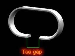
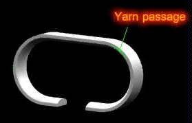
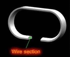
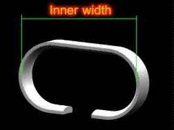
Height of bow: It should be as low as possible for stable running of traveller. It should also have sufficient yarn pasage. Yarn passage: According to count spun the traveller profile to be selected with required yarn passage. Toe gap : This will vary according to traveller number and flange width of the ring Wire section: It plays an important role for yarn quality, life of traveller. Ring contact area: This area should be more, uniform, smooth and continuous for best performance. Inner width: This varies according to traveller profile and ring flange. .
SALIENT FEATURES OF A TRAVELLER:
When the spindle speed is increased, the friction work between ring and traveller (hence the build up) increases as the 3rd power of the spindle rpm. Consequently if the spindle speed is too high, the traveller sustains thermal damage and fails. This speed restriction is felt particularly when spinning cotton yarns of relatively high strength. - If the traveller speed is raised beyond normal levels , the thermal stress limit of the traveller is exceeded, a drastic change in the wear behaviour of the ring and traveller ensues. Owing to the strongly increased adhesion forces between ring and traveller, welding takes place between the two. These seizures inflict massive damage not only to the traveller but to the ring as well. The spinning tension is proportional
and inversely proportional
The coefficient of friction with fiber lubrication can vary from 0.03 and 0.15. R = Co efficeint of friction x N where R - traveller friction in mN N = Normal force >= (Fc x ML x V xV)/(R) Fc - centrifugal force ML - mass of the traveller in mg V - traveller speed in m/s R - radius of the ring (inside)
TECHNOLOGICAL GUIDELINES:
Preconditions for good operating results The maximum ability of the ring/traveller system to withstand occuring stress situation during operation determines the performance limit of the ring spinning and twisting machine. Traveller wear does not only depend on traveller material; problems of heat dissipation are of crucial importance, too. The heat generated between ring and traveller must be reduced as quickly as possible to avoid local temperature in the traveller wear zones. The ability of the traveller to resist to stress is determined by several factors. Investigations regarding improvements of rings and travellers aimed at a further increase of performance should above all make sure that all other conditions with a certain influence on the spinning process are optimal. Therefore make sure that: ¥ the rings are correctly centered with regard to the spindles ¥ the yarn guide eyelet is well centered with regard to the spindle ¥ the spindle bearing is in good condition, thus preventing spindle vibrations ¥ the ratio between bobbin diameter and ring diameter is correct ¥ the concentricity of the ballon control ring with regard to the spindle is correct ¥ the fibre tufts which accumulate on flange travellers are removed by means of suitable traveller cleaners ¥ the climatic conditions (temperature and relative air humidity) are favourable for the spinning process ¥ the air in the mill is free from disturbing particles that influence efficient performance of the traveller It has to be stressed that a smooth and well run-in track is of most importance. Concentricity of spindle, ring, yarn guide and balloon control ring Especially at high spindle speeds concentric positioning of ring, spindle, yarn eyelet and balloon control ring is required for keeping the ends down rate at low level. Spindles and rings must be aligned and centered absolutely parallel. Ring rails or ring holders should, therefore, be installed absolutely horizontally compared to the vertically fitted spindles. Ring and traveller form the main elements in ring spinning and twisting. They determine to a large extent performance and operating conditions of the machine. The traveller accomplishes two main tasks while running on the ring at high speeds: a) It gives the roving supplied by the feed rollers the necessary twist. b) It assists in winding the yarn onto the bobbin in the form of a cop with ã correct tension. During this operation the ring guides the traveller, which is essential for the perfect positioning of the yarn and the formation of the cop. The traveller is pressed against the ring track by centrifugal forces. The resulting frictional forces reduce traveller speed, which is dragged along by the passing-through yarn, and provide the yarn with the tensile forces necessary for assembling the individual fibres into the spun yarn as well as for limiting the yarn balloon. Steel travellers are hardened to a certain degree and polished to a mirror finish. They can be adapted in shape, weight and surface finish to the ring, yarn type and yarn count. Nylon travellers of standard quality (for HZ and J rings) are made of highly wear-resistant polyamide. Extremely aggressive yarns are processed with glass-fibre-reinforced a Super Nylon travellers. Twisting and winding carried out by the traveller must be performed with appropriate yarn tension. The ratio between spindle speed and the speed at which the yarn is supplied determines yarn twist. Any change of this ratio is easily compensated by the traveller without having an influence on twisting, winding and tensioning. On flange rings, the gliding speed of travellers having a suitable shape can be as rapid as 130 ft/s (88 MPH) or 40 m/s (140 km/h); on DIA-DUR coated rings the speed can to some extent reach 147 ft/s (100 MPH) or 45 m/s (160 km/h) . Having an average life span of 200-300 operating hours the traveller covers a distance of more than 18.000 miles (30.000 km) - a tremendous task for a small part of wire weighing only a few milligrams. These standards can even be surpassed by nylon travellers used on HZ rings, if operating conditions are favourable. These high traveller speeds involve pressures of up to 35 N/mm 2 . But even if high-quality materials with an optimum of hardness and resistance to wear are used, these standards can only be reached if ¥ in the case of flange rings, a film of lubricating fibres is produced continuously, ¥ in the case of HZ and J rings, a sufficient amount of lubricant is consistently provided. d 1 = spinning ring diameter d 2 = fitting diameter h 1 = ring height h 2 = ring height above ring rail b = flange width flange 1 = 3.2 mm flange 2 = 4.1 mm Spindles operating without vibrations contribute a great deal to a smooth operation of the traveller. Non-concentric spindles and spindles not running smoothly cause constant changes in yarn tension , because the traveller cannot run around the ring without being shaken. Vibration-free movements of ring rail and ring holder Correct ratio between bobbin diameter, bobbin length, ring diameter and spindle gauge Ratio bobbin length (H) : Inside ring diameter (D) Thread tension increases with growing bobbin length. In view of the limited thread tension, the total bobbin length should not exceed 5 times the ring diameter. Only when using balloon control rings or similar devices this value can be exceeded. H : D = 5 : 1 Ratio bobbin diameter (d) : Inside ring diameter (D) The bobbin diameter d is equivalent to the mean outer bobbin diameter d 1 + d 2 The following values are recommended: for spinning: d : D = 0.48 - 0.5 (a = 29°-30°), (minimum value a = 26°) for twisting d : D = 0.44 - 0.5 (a = 27°-30°), (minimum value a = 22°) For light and heavy bobbins, the values for light bobbin types are decisive for calculating d : D. If the ratio d : D is reduced thread tension increases. Correct surface smoothness, i.e. optimum peak-to-valley height and evenness of the ring track The traveller contact surfaces must be smooth and even. Only then a smooth operation of the traveller will be possible. The contacted surfaces should be clean and preferably without traces of wear. In addition, they should be designed in such a way that they offer sufficient adherence for potential lubricants (e.g. fibres, oil, grease). Once the sliding surfaces have lost their original quality, even the best ring traveller will not be able to run smoothly. For maintaining the surface of the running track in a good condition, it is very important - besides a certain degree of maintenance - to run the ring well in. Balloon control rings and separators The influence of balloon control rings is quite considerable, especially at long cops. A reduction of the yarn balloon is advantageous or may even be the prerequisite for optimum performance. If balloon control rings are mounted at correct distance (the yarn balloon should be restricted as long as possibleduring one lift of the ring rail) then a marked performance increase is possible. The balloon control rings are removed when sensitive materials are processed and sufficiently long separators are installed to avoid many yarn breaks and to prevent fibre fly from accumulating on the adjacent spindles. Traveller cleaners Traveller cleaners are an excellent method for removing all fibre fly that accumulates on the outer part of C and El travellers. The traveller cleaner should have the right distance to the outside ring flange. A distance of about 0.5 mm between cleaner and traveller (in operating position) is recommended. When adjusting the distance between outside ring flange and cleaner, the size of the traveller should be taken into consideration. Room climate Constant temperature and air humidity have positive effects on the operation of the traveller. Changes of the room climate, such as raised air humidity will increase wear by friction. Besides the regular exchange of air, the purity of the air is of great importance for the traveller. Any dust (also dust from unsuitable floors) or other impurities may impair traveller operation and lead to more ring/traveller wear. Flange width and ring height Optimal operating results are reached when the ideal flange width is chosen for flange rings and the ideal ring height is obtained for self-lubricating HZ and J rings, dependent on yarn count range, yarn quality and traveller type. Ring profile and traveller shape Determining the most favourable ring and traveller shapes is a precondition for obtaining the optimal individual performance. If ring profile and traveller shape match well, the traveller will adopt a stable position in the ring. It should have sufficient tolerance of movement, so that any obstacles which may occur especially when the machine is started are avoided. A satisfactory large yarn clearance counteracts yarn breaks and yarn damage. Running-in of rings Normally the running-in procedure is decisive for the future positive/nega tive behaviour of the ring and the length of its service life. Every ring requires a certain degree of running-in time if it is to maintain high traveller speeds with as little ring and traveller wear as possible. During running-in the use of steel travellers without surface treatment is recommended. After the termination of the running-in process, steel travellers with surface treatment or nylon as well as bronze travellers can be used. The running-in process, beginning with the starting phase, consists of improving the initial running properties of the metallic running surface up to the optimal values by smoothing and passivation(oxidation) as soon as possible. In this way, together with fibre lubrication, constant minimum mixed friction conditions and minimum thermal stressing can be attained for the ring traveller. A careful running-in process will improve the lifetime of the rings. In order to keep the stress on the traveller as low as possible during the starting phase, it is advisable to always change the traveller in the upper third part of the cops. Further advantages are brought with the use of a traveller running-in program(reduction of the speed by about 10% for 10 to 20 minutes, only available on modern spinning machines). Spindle speed should be reduced atleast for the first 10 traveller changes. If final speed is higher than 32m/sec, reduce by atleast 20%. If final speed is lower than 32m/sec, reduce by at least 10%. New rings should not be degreased, but only rubbed over with a dry cloth. In general, the running in should be done with the same traveller type which is used for normal operation with the 10 to 20% less than normal speed. It is not advisable to do running with the same speed but with 1to 2 numbers lighter travellers than usual. The first traveller change should be carried out after 15 min The second traveller chage should take place after 30 min The third traveller change should be made after 1 to 1.5 hours. The fourth traveller change should be made after the first doff. Further traveller changes are to be made according to the manufacturers recommendations
HAIRINESS: Following are the reasons for higher yarn hairiness due to ring and travellers
Poorly centered spindles, anti balloon rings and yarn guides lead to inconsistent yarn tension. Rough surfaces roughen the yarn(due to damaged parts) Open anti balloon ring The clearance between ring and cop should not be too small. Traveller will cut the fibres protruding from the cop. the fibres get electrostatically charged poor twist propagation to the spinning triangle due to lighter travellers Heavy friction of the balloon on the anti-balloon ring respectively impact on the balloon separator( due to lighter traveller) Poor ring centering crooked tubes yarn getting roughened in narrow yarn passage in the traveller scratched up yarn passages catch the yarn and roughen it (due to very high traveller running time) friction of the yarn due to very high traveller weight rough gliding surface of the ring ( due to worn out rings) |

