1. Introduction: The Induction motor is a three phase AC motor and is the most widely used machine. Its characteristic features are-
- Simple and rugged construction
- Low cost and minimum maintenance
- High reliability and sufficiently high efficiency
- Needs no extra starting motor and need not be synchronized
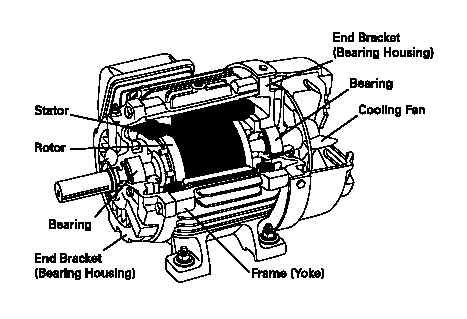
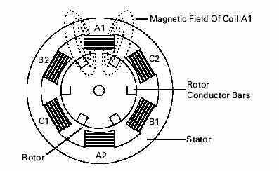
An Induction motor has basically two parts – Stator and Rotor
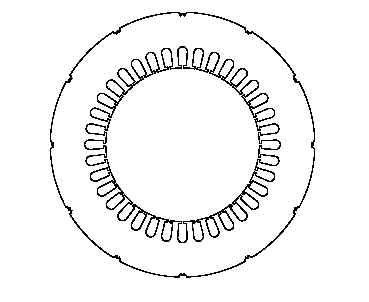
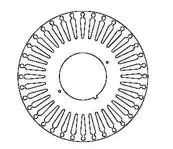
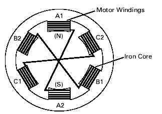
The Stator is made up of a number of stampings with slots to carry three phase windings. It is wound for a definite number of poles. The windings are geometrically spaced 120 degrees apart. Two types of rotors are used in Induction motors - Squirrel-cage rotor and Wound rotor.
INDUCTION MOTOR:
| All loads moved by electric motors are really moved by magnetism. The purpose of every component in a motor is to help harness, control, and use magnetic force. When applying an AC drive system it helps to remember you are actually applying magnets to move a load. To move a load fast does not require more magnets, you just move the magnets fast. To move a heavier load or to decrease acceleration time (accelerate faster) more magnets (more torque) are needed. This is the basis for all motor applications. |
STATOR CONSTRUCTION:
The stator and the rotor are electrical circuits that perform as electromagnets. The stator is the stationary electrical part of the motor. The stator core of a NEMA motor is made up of several hundred thin laminations.
STATOR WINDINGS;
Stator laminations are stacked together forming a hollow cylinder. Coils of insulated wire are inserted into slots of the stator core.
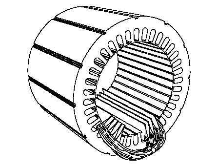
Each grouping of coils, together with the steel core it surrounds, form an electromagnet.
ROTOR CONSTRUCTION:
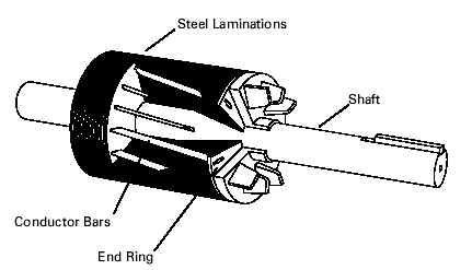
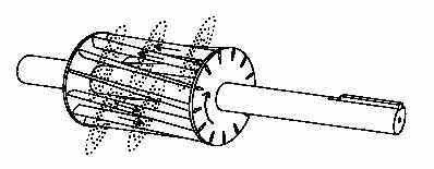
The rotor is the rotating part of the electromagnetic circuit. The most common type of rotor is the "squirrel cage" rotor. Other types of rotor construction will be mentioned later in the course. The construction of the squirrel cage rotor is reminiscent of rotating exercise wheels found in cages of pet rodents.
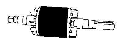
The rotor consists of a stack of steel laminations with evenly spaced conductor bars around the circumference.
The laminations are stacked together to form a rotor core. Aluminum is die cast in the slots of the rotor core to form a series of conductors around the perimeter of the rotor. Current flow through the conductors form the electromagnet. The conductor bars are mechanically and electrically connected with end rings. The rotor core mounts on a steel shaft to form a rotor assembly.
ENCLOSURE:
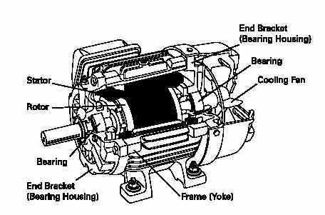
The enclosure consists of a frame (or yoke) and two end brackets (or bearing housings). The stator is mounted inside the frame. The rotor fits inside the stator with a slight air gap separating it from the stator. There is no direct physical connection between the rotor and the stator. The enclosure also protects the electrical and operating parts of the motor from harmful effects of the environment in which the motor operates. Bearings, mounted on the shaft, support the rotor and allow it to turn. A fan, also mounted on the shaft, is used on the motor shown below for cooling.
ELECTROMAGNETISM:
When current flows through a conductor a magnetic field is produced around the conductor. The magnetic field is made up of lines of flux, just like a natural magnet. The size and strength of the magnetic field will increase and decrease as the current flow strength increases and decreases.
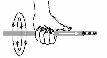
LEFT HAND RULE FOR CONDUCTORS:
A definite relationship exists between the direction of current flow and the direction of the magnetic field. The left-hand rule for conductors demonstrates this relationship. If a currentcarrying conductor is grasped with the left hand with the thumb pointing in the direction of electron flow, the fingers will point in the direction of the magnetic lines of flux.
ELECTROMAGNET:
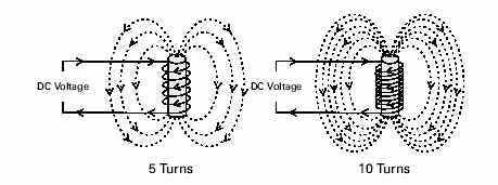
An electromagnet can be made by winding the conductor into a coil and applying a DC voltage. The lines of flux, formed by current flow through the conductor, combine to produce a larger and stronger magnetic field. The center of the coil is known as the core. In this simple electromagnet the core is air.
Iron is a better conductor of flux than air. The air core of an electromagnet can be replaced by a piece of soft iron. When a piece of iron is placed in the center of the coil more lines of flux can flow and the magnetic field is strengthened.
-
NO OF TURNS:
The strength of the magnetic field in the DC electromagnet can be increased by increasing the number of turns in the coil. The greater the number of turns the stronger the magnetic field will be.
CHANGING POLARITY:
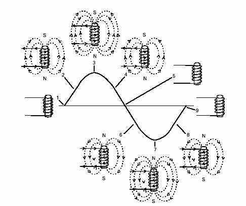
The magnetic field of an electromagnet has the same characteristics as a natural magnet, including a north and south pole. However, when the direction of current flow through the electromagnet changes, the polarity of the electromagnet changes. The polarity of an electromagnet connected to an AC source will change at the same frequency as the frequency of the AC source. This can be demonstrated in the following illustration. At Time 1 current flow is at zero. There is no magnetic field produced around the electromagnet. At Time 2 current is flowing in a positive direction. A magnetic field builds up around the electromagnet. The electromagnet assumes a polarity with the south pole on the top and the north pole on the bottom. At Time 3 current flow is at its peak positive value. The strength of the electromagnetic field is at its greatest value. At Time 4 current flow decreases and the magnetic field begins to collapse, until Time 5 when current flow and magnetic field are at zero. Current immediately begins to increase in the opposite direction. At Time 6 current is increasing in a negative direction. The polarity of the electromagnetic field has changed. The north pole is now on top and the south pole is on the bottom. The negative half of the cycle continues through Times 7 and 8, returning to zero at Time 9. This process will repeat 60 times a second with a 60 Hz AC power supply.
INDUCED VOLTAGE:
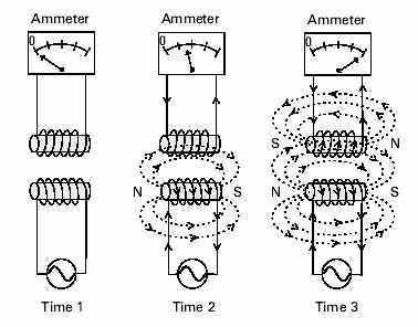
A conductor moving through a magnetic field will have a voltage induced into it. This electrical principle is used in the operation of AC induction motors. In the following illustration an electromagnet is connected to an AC power source. Another electromagnet is placed above it. The second electromagnet is in a separate circuit. There is no physical connection between the two circuits. Voltage and current are zero in both circuits at Time 1. At Time 2 voltage and current are increasing in the bottom circuit. A magnetic field builds up in the bottom electromagnet. Lines of flux from the magnetic field building up in the bottom electromagnet cut across the top electromagnet. A voltage is induced in the top electromagnet and current flows through it. At Time 3 current flow has reached its peak. Maximum current is flowing in both circuits. The magnetic field around the coil continues to build up and collapse as the alternating current continues to increase and decrease. As the magnetic field moves through space, moving out from the coil as it builds up and back towards the coil as it collapses, lines of flux cut across the top coil. As current flows in the top electromagnet it creates its own magnetic field.
ELECTROMAGNETIC ATTRACTION:
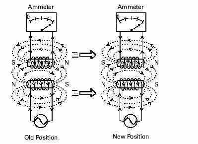
The polarity of the magnetic field induced in the top electromagnet is opposite the polarity of the magnetic field in the bottom electromagnet. Since opposite poles attract, the top electromagnet will follow the bottom electromagnet when it is moved.
DEVELOPING A ROTATING MAGENETIC FIELD:
The principles of electromagnetism explain the shaft rotation of an AC motor. Recall that the stator of an AC motor is a hollow cylinder in which coils of insulated wire are inserted.
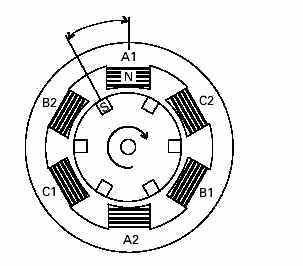
STATOR COIL ARRANGEMENT:
The following schematic illustrates the relationship of the coils. In this example six coils are used, two coils for each of the three phases. The coils operate in pairs. The coils are wrapped around the soft iron core material of the stator. These coils are referred to as motor windings. Each motor winding becomes a separate electromagnet. The coils are wound in such a way that when current flows in them one coil is a north pole and its pair is a south pole. For example, if A1 were a north pole then A2 would be a south pole. When current reverses direction the polarity of the poles would also reverse.
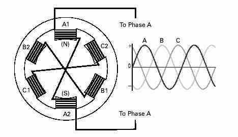
POWER SUPPLY:
The stator is connected to a 3-phase AC power supply. In the following illustration phase A is connected to phase A of the power supply. Phase B and C would also be connected to phases B and C of the power supply respectively.
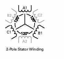
Phase windings (A, B, and C) are placed 120° apart. In this example, a second set of three-phase windings is installed. The number of poles is determined by how many times a phase winding appears. In this example, each phase winding appears two times. This is a two-pole stator. If each phase winding appeared four times it would be a four-pole stator.
When AC voltage is applied to the stator, current flows through the windings. The magnetic field developed in a phase winding depends on the direction of current flow through that winding. The following chart is used here for explanation only. It will be used in the next few illustrations to demonstrate how a rotating magnetic field is developed. It assumes that a positive current flow in the A1, B1 and C1 windings result in a north pole.
| Winding | Current Flow Direction | |
| Positive | Negative | |
| A1 | North | South |
| A2 | South | North |
| B1 | North | South |
| B2 | South | North |
| C1 | North | South |
| C2 | South | North |
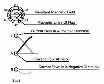
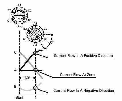
START:
It is easier to visualize a magnetic field if a start time is picked when no current is flowing through one phase. In the following illustration, for example, a start time has been selected during which phase A has no current flow, phase B has current flow in a negative direction and phase C has current flow in a positive direction. Based on the above chart, B1 and C2 are south poles and B2 and C1 are north poles. Magnetic lines of flux leave the B2 north pole and enter the nearest south pole, C2. Magnetic lines of flux also leave the C1 north pole and enter the nearest south pole, B1. A magnetic field results, as indicated by the arrow.
TIME 1:
If the field is evaluated at 60° intervals from the starting point, at Time 1, it can be seen that the field will rotate 60°. At Time 1 phase C has no current flow, phase A has current flow in a positive direction and phase B has current flow in a negative direction. Following the same logic as used for the starting point, windings A1 and B2 are north poles and windings A2 and B1 are south poles.
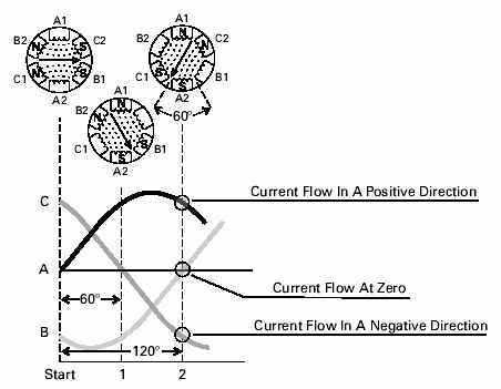
TIME 2:
At Time 2 the magnetic field has rotated 60°. Phase B has no current flow.
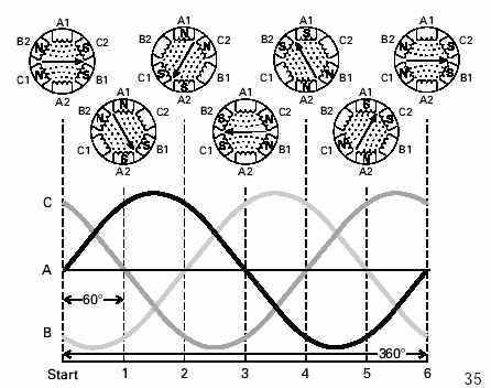
360 degree ROTATION:
At the end of six such time intervals the magnetic field will have rotated one full revolution or 360°. This process will repeat 60 times a second on a 60 Hz power supply.
SYNCHRONOUS SPEED:
The speed of the rotating magnetic field is referred to as synchronous speed (NS). Synchronous speed is equal to 120 times the frequency (F), divided by the number of poles (P).
Ns = 120 F / P
If the frequency of the applied power supply for the two-pole stator used in the previous example is 60 Hz, synchronous speed is 3600 RPM.
N s =( 120 x 60 )/ 2
N = 3600 RPM
The synchronous speed decreases as the number of poles increase. The following table shows the synchronous speed at 60 Hz for the corresponding number of poles.
| no of poles | synchronous speed |
| 2 | 3600 |
| 4 | 1800 |
| 6 | 1200 |
| 8 | 900 |
| The magnetic field rotates at synchronous speed, VS—the motor’s theoretical top speed that would result in no torque output. In actual operation, rotor speed always lags the magnetic field’s speed, allowing the rotor bars to cut magnetic lines of force and produce useful torque. This speed difference is called slip speed. Typical slip values range 2-5% of VS at running speed, but can be large at motor startup. Slip also increases with load, so for accurate control of speed, closed-loop control or feedback is needed. |
ROTOR ROTATION:
PERMANENT MAGNET:
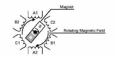
To see how a rotor works, a magnet mounted on a shaft can be substituted for the squirrel cage rotor. When the stator windings are energized a rotating magnetic field is established. The magnet has its own magnetic field that interacts with the rotating magnetic field of the stator. The north pole of the rotating magnetic field attracts the south pole of the magnet, and the south pole of the rotating magnetic field attracts the north pole of the magnet. As the rotating magnetic field rotates, it pulls the magnet along causing it to rotate. This design, used on some motors, isreferred to as a permanent magnet synchronous motor.
INDUCED VOLTAGE ELECTROMAGNET:
The squirrel cage rotor acts essentially the same as the magnet. When power is applied to the stator, current flows through the winding, causing an expanding electromagnetic field which cuts across the rotor bars.
When a conductor, such as a rotor bar, passes through a magnetic field a voltage (emf) is induced in the conductor. The induced voltage causes a current flow in the conductor. Current flows through the rotor bars and around the end ring. The current flow in the conductor bars produces magnetic fields around each rotor bar. Recall that in an AC circuit current continuously changes direction and amplitude. The resultant magnetic field of the stator and rotor continuously change. The squirrel cage rotor becomes an electromagnet with alternating north and south poles.
The following drawing illustrates one instant in time during which current flow through winding A1 produces a north pole. The expanding field cuts across an adjacent rotor bar, inducing a voltage. The resultant magnetic field in the rotor tooth produces a south pole. As the stator magnetic field rotates the rotor follows.
SLIP:
There must be a relative difference in speed between the rotor and the rotating magnetic field. If the rotor and the rotating magnetic field were turning at the same speed no relative motion would exist between the two, therefore no lines of flux would be cut, and no voltage would be induced in the rotor. The difference in speed is called slip. Slip is necessary to produce torque. Slip is dependent on load. An increase in load will cause the rotor to slow down or increase slip. A decrease in load will cause the rotor to speed up or decrease slip. Slip is expressed as a percentage and can be determined with the following formula.
% Slip = (Ns - Nr) x 100/Ns
For example, a four-pole motor operated at 60 Hz has a synchronous speed (NS) of 1800 RPM. If the rotor speed at full load is 1765 RPM (NR), then slip is 1.9%.
% Slip = (1800 - 1765) x 100 / 1800
% Slip = 1.9%
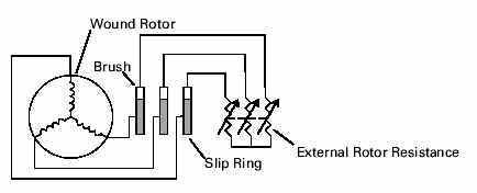
WOUND ROTOR MOTOR:
The discussion to this point has been centered on the more common squirrel cage rotor. Another type is the wound rotor. A major difference between the wound rotor motor and the squirrel cage rotor is the conductors of the wound rotor consist of wound coils instead of bars. These coils are connected through slip rings and brushes to external variable resistors. The rotating magnetic field induces a voltage in the rotor windings. Increasing the resistance of the rotor windings causes less current flow in the rotor windings, decreasing speed. Decreasing the resistance allows more current flow, speeding the motor up.
SYNCHRONOUS MOTOR:
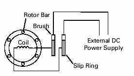
Another type of AC motor is the synchronous motor. The synchronous motor is not an induction motor. One type of synchronous motor is constructed somewhat like a squirrel cage rotor. In addition to rotor bars coil windings are added. The coil windings are connected to an external DC power supply by slip rings and brushes. On start AC is applied to the stator and the synchronous motor starts like a squirrel cage rotor. DC is applied to the rotor coils after the motor reaches maximum speed. This produces a strong constant magnetic field in the rotor which locks in step with the rotating magnetic field. The rotor turns at the same speed as synchronous speed (speed of the rotating magnetic field). There is no slip. Variations of synchronous motors include a permanent magnet rotor. The rotor is a permanent magnet and an external DC source is not required. These are found on small horsepower synchronous motors.
| Induction motors have five major components of loss; Iron loss, Copper loss, Frictional loss, Windage loss and Sound loss. All these losses add up to the total loss of the induction motor. Frictional loss, windage loss and sound loss are constant, independent of shaft load, and are typically very small. The major losses are Iron loss and Copper Loss. The iron loss is essentially constant, independent of shaft load, while the copper loss is an I2R loss which is shaft load dependent. The iron loss is voltage dependent and so will reduce with reducing voltage. |
REFERENCE: SIEMENS GUIDELINES TO CUSTOMER