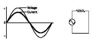
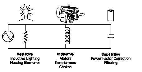
. RESISITVE LOADS:Resistive loads include devices such as heating elements and incandescent lighting. In a purely resistive circuit, current and voltage rise and fall at the same time. They are said to be "in phase."
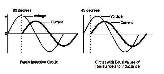
TRUE POWER:All the power drawn by a resistive circuit is converted to usefulwork. This is also known as true power in a resistive circuit. Truepower is measured in watts (W), kilowatts (kW), or megawatts(MW). In a DC circuit or in a purely resistive AC circuit, truepower can easily be determined by measuring voltage and current. True power in a resistive circuit is equal to system voltage (E) times current (I). INDUCTIVE LOADS:Inductive loads include motors, transformers, and solenoids. In a purely inductive circuit, current lags behind voltage by 90°.Current and voltage are said to be "out of phase." Inductive circuits, however, have some amount of resistance. Depending on the amount of resistance and inductance, AC current will lag somewhere between a purely resistive circuit (0°) and a purely inductive circuit (90°). In a circuit where resistance and inductance are equal values, for example, current lags voltageby 45°.
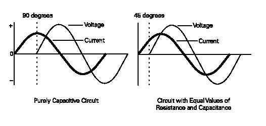
CAPACITIVE LOADS:.
Capacitive loads include power factor correction capacitors and filtering capacitors. In a purely capacitive circuit, current leads voltage by 90°. Capacitive circuits, however, have some amount of resistance. Depending on the amount of resistance and capacitance, AC current will lead voltage somewhere between a purely resistive circuit (0°) and a purely capacitive circuit (90°).In a circuit where resistance and capacitance are equal values,for example, current leads voltage by 45°.
REACTIVE LOADS:Circuits with inductive or capacitive components are said to be reactive. Most distribution systems have various resistive and reactive circuits. The amount of resistance and reactance varies,depending on the connected loads.
REACTANCE: Just as resistance is opposition to current flow in a resistive circuit, reactance is opposition to current flow in a reactive circuit. It should be noted, however, that where frequency has no effect on resistance, it does effect reactance. An increase in applied frequency will cause a corresponding increase in inductive reactance and a decrease in capacitive reactance. For resistance R = E/I, Where R = resistance in Ohms, E = voltage and I = current For inductive Reactance XL = 2 x 3.14 x f x L , where XL is inductive reactance in ohms, f = applied freq and L = inductance in henrys For Capacitive reactance XC = 1 / (2 x 3.14 x f x C) where XC =capacitive reactance, f = applied freq and C = capacitance in farads
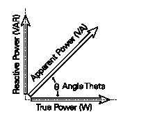
ENERGY IN REACTIVE CIRUCUITS:Energy in a reactive circuit does not produce work. This energy is used to charge a capacitor or produce a magnetic field around the coil of an inductor. Current in an AC circuit rises to peak values (positive and negative) and diminishes to zero many times a second. During the time, current is rising to a peakvalue, energy is stored in an inductor in the form of a magnetic field or as an electrical charge in the plates of a capacitor. REACTIVE POWER Power in an AC circuit is made up of three parts; true power,reactive power, and apparent power. We have already discussed true power. Reactive power is measured in volt-amps reactive(VAR). Reactive power represents the energy alternately stored and returned to the system by capacitors and/or inductors.Although reactive power does not produce useful work, it still needs to be generated and distributed to provide sufficient true power to enable electrical processes to run. APPARENT POWER: Not all power in an AC circuit is reactive. We know that reactive power does not produce work; however, when a motor rotates work is produced. Inductive loads, such as motors, have some amount of resistance. Apparent power represents a load which includes reactive power (inductance) and true power(resistance). Apparent power is the vector sum of true power,which represents a purely resistive load, and reactive power,which represents a purely reactive load. A vector diagram can be used to show this relationship. The unit of measurement for apparent power is volt amps (VA). Larger values can be stated inkilovolt amps (kVA) or megavolt amps (MVA).
POWER AND POWER FACTOR IN AN AC CIRCUIT: Power consumed by a resistor is dissipated in heat and not returned to the source. This is true power. True power is the rate at which energy is used. Current in an AC circuit rises to peak values and diminishes to zero many times a second. The energy stored in the magnetic field of an inductor, or plates of a capacitor, is returned to the source when current changes direction. Power in an AC circuit is the vector sum of true power and reactive power. This is called apparent power.True power is equal to apparent power in a purely resistive circuit because voltage and current are in phase. Voltage and current are also in phase in a circuit containing equal values of inductive reactance and capacitive reactance. If voltage and current are 90 degrees out of phase, as would be in a purely capacitive or purely inductive circuit, the average value of true power is equal to zero. There are high positive and negative peak values of power, but when added together the result is zero. The formula for apparent power is: P = EI Apparent power is measured in volt-amps (VA).True power is calculated from another trigonometric function,the cosine of the phase angle (cos q). The formula for truepower is: P = EI cos q True power is measured in watts. In a purely resistive circuit, current and voltage are in phase.There is a zero degree angle displacement between current and voltage. The cosine of zero is one. Multiplying a value by one does not change the value. In a purely resistive circuit the cosine of the angle is ignored.In a purely reactive circuit, either inductive or capacitive,current and voltage are 90 degrees out of phase. The cosine of 90 is zero. Multiplying a value times zero results in a zero product. No power is consumed in a purely reactive circuit.
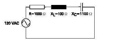
CALCULATING APPARENT POWER IN A SIMPLE R-L-C CIRCUIT:
In the following 120 volt circuit, It is equal to 84.9 milliamps.Inductive reactance is 100 W and capacitive reactance is1100 W. The phase angle is -45 degrees. By referring to atrigonometric table, the cosine of -45 degrees is foundto be .7071. The apparent power consumed by the cirucuit is P = EI P = 10.2 VA The true power consumed by the ciruit is P= EI COS (phi) = 120 x 0.0849 x 0.7071 = 7.2 watts another formula for true power is
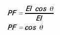
P = 0.0849 X 0.0849 X 1000 = 7.2 watts POWER FACTOR: Power factor is the ratio of true power to apparent power in an AC circuit. Power factor is expressed in the following formula: PF = PT/PA Power factor can also be expressed using the formulas for true power and apparent power. The value of EI cancels out because it is the same in the numerator and denominator.Power factor is the cosine of the angle.
In a purely resistive circuit, where current and voltage are inphase, there is no angle of displacement between current and voltage. The cosine of a zero degree angle is one. The powerfactor is one. This means that all energy delivered by the source is consumed by the circuit and dissipated in the form of heat.In a purely reactive circuit, voltage and current are 90 degrees apart. The cosine of a 90 degree angle is zero. The powerfactor is zero. This means the circuit returns all energy it receives from the source to the source.In a circuit where reactance and resistance are equal, voltage and current are displaced by 45 degrees. The cosine of a 45degree angle is .7071. The power factor is .7071. This means the circuit has used approximately 70% of the energy supplied by the source and returned approximately 30%. LEADING AND LAGGING POWER FACTOR: Since current leads voltage in a capacitive circuit, power factor is considered leading if there is more capacitive reactance than inductive reactance. Power factor is considered lagging if there is more inductive reactance than capacitive reactance since current lags voltage in an inductive circuit. Power factor is unity when there is no reactive power or when inductive reactance and capacitive reactance are equal, effectively cancelling eachother. It is usually more economical to correct poor power factor than to pay large utility bills. In most industrial applications motors account for approximately 60% or more of electric power consumption, resulting in a lagging power factor (more inductive than capacitive). Power factor correction capacitors can be added to improve the power factor. POWER FACTOR PROBLEMS: It can be seen that an increase in reactive power causes a corresponding decrease in power factor. This means the power distribution system is operating less efficiently because not all current is performing work. For example, a 50 kW load with a power factor of 1 (reactive power = 0) could be supplied by a transformer rated for 50 kVA. However, if power factor is 0.7(70%) the transformer must also supply additional power for the reactive load. In this example a larger transformer capable ofsupplying 71.43 kVA (50 ÷ 70%) would be required. In addition,the size of the conductors would have to be increased, adding significant equipment cost. Power Factor.Power factor is the ratio between the KW and the KVA drawn by an electrical load where the KW is the actual load power and the KVA is the apparent load power. It is a measure of how effectively the current is being converted into useful work output and more particularly is a good indicator of the effect of the load current on the efficiency of the supply system. All current will causes losses in the supply and distribution system. A load with a power factor of 1.0 results in the most efficient loading of the supply and a load with a power factor of 0.5 will result in much higher losses in the supply system. A poor power factor can be the result of either a significant phase difference between the voltage and current at the load terminals, or it can be due to a high harmonic content or distorted/discontinuous current waveform. Poor load current phase angle is generally the result of an inductive load such as an induction motor, power transformer, lighting balasts, welder or induction furnace. A distorted current waveform can be the result of a rectifier, variable speed drive, switched mode power supply, discharge lighting or other electronic load. A poor power factor due to an inductive load can be improved by the addition of power factor correction, but, a poor power factor due to a distorted current waveform requires an change in equipment design or expensive harmonic filters to gain an appreciable improvement. Many inverters are quoted as having a power factor of better than 0.95 when in reality, the true power factor is between 0.5 and 0.75. The figure of 0.95 is based on the Cosine of the angle between the voltage and current but does not take into account that the current waveform is discontinuous and therefore contributes to increased losses on the supply. Power Factor Correction.Capacitive Power Factor correction is applied to circuits which include induction motors as a means of reducing the inductive component of the current and thereby reduce the losses in the supply. There should be no effect on the operation of the motor itself. An induction motor draws current from the supply, that is made up of resistive components and inductive components. The resistive components are: 1) Load current. 2) Loss current. and the inductive components are: 3) Leakage reactance. 4) Magnetising current. The current due to the leakage reactance is dependant on the total current drawn by the motor, but the magnetising current is independent of the load on the motor. The magnetising current will typically be between 20% and 60% of the rated full load current of the motor. The magnetising current is the current that establishes the flux in the iron and is very necessary if the motor is going to operate. The magnetising current does not actually contribute to the actual work output of the motor. It is the catalyst that allows the motor to work properly. The magnetising current and the leakage reactance can be considered passenger components of current that will not affect the power drawn by the motor, but will contribute to the power dissipated in the supply and distribution system. Take for example a motor with a current draw of 100 Amps and a power factor of 0.75 The resistive component of the current is 75 Amps and this is what the KWh meter measures. The higher current will result in an increase in the distribution losses of (100 x 100) /(75 x 75) = 1.777 or a 78% increase in the supply losses. In the interest of reducing the losses in the distribution system, power factor correction is added to neutralise a portion of the magnetising current of the motor. Typically, the corrected power factor will be 0.92 - 0.95 Some power retailers offer incentives for operating with a power factor of better than 0.9, while others penalise consumers with a poor power factor. Power factor correction is achieved by the addition of capacitors in parallel with the connected motor circuits and can be applied at the starter, or applied at the switchboard or distribution panel. The resulting capacitive current is leading current and is used to cancel the laging inductive current flowing from the supply. Capacitors connected at each starter and controlled by each starter is known as "Static Power Factor Correction" while capacitors connected at a distribution board and controlled independently from the individual starters is known as "Bulk Correction". BULK CORRECTION: The Power factor of the total current supplied to the distribution board is monitored by a controller which then switches capacitor banks In a fashion to maintain a power factor better than a preset limit. (Typically 0.95) Ideally, the power factor should be as close to unity as possible. There is no problem with bulk correction operating at unity. STATIC CORRECTION: As a large proportion of the inductive or lagging current on the supply is due to the magnetising current of induction motors, it is easy to correct each individual motor by connecting the correction capacitors to the motor starters. With static correction, it is important that the capacitive current is less than the inductive magnetising current of the induction motor. In many installations employing static power factor correction, the correction capacitors are connected directly in parallel with the motor windings. When the motor is Off Line, the capacitors are also Off Line. When the motor is connected to the supply, the capacitors are also connected providing correction at all times that the motor is connected to the supply. This removes the requirement for any expensive power factor monitoring and control equipment. In this situation, the capacitors remain connected to the motor terminals as the motor slows down. An induction motor, while connected to the supply, is driven by a rotating magnetic field in the stator which induces current into the rotor. When the motor is disconnected from the supply, there is for a period of time, a magnetic field associated with the rotor. As the motor decelerates, it generates voltage out its terminals at a frequency which is related to it's speed. The capacitors connected across the motor terminals, form a resonant circuit with the motor inductance. If the motor is critically corrected, (corrected to a power factor of 1.0) the inductive reactance equals the capacitive reactance at the line frequency and therefore the resonant frequency is equal to the line frequency. If the motor is over corrected, the resonant frequency will be below the line frequency. If the frequency of the voltage generated by the decelerating motor passes through the resonant frequency of the corrected motor, there will be high currents and voltages around the motor/capacitor circuit. This can result in sever damage to the capacitors and motor. It is imperative that motors are never over corrected or critically corrected when static correction is employed. Static power factor correction should provide capacitive current equal to 80% of the magnetising current, which is essentially the open shaft current of the motor. The magnetising current for induction motors can vary considerably. Typically, magnetising currents for large two pole machines can be as low as 20% of the rated current of the motor while smaller low speed motors can have a magnetising current as high as 60% of the rated full load current of the motor. It is not practical to use a "Standard table" for the correction of induction motors giving optimum correction on all motors. Tables result in undercorrection on most motors but can result in over correction in some cases. Where the open shaft current can not be measured, and the magnetising current is not quoted, an approximate level for the maximum correction that can be applied can be calculated from the half load characteristics of the motor. It is dangerous to base correction on the full load characteristics of the motor as in some cases, motors can exhibit a high leakage reactance and correction to 0.95 at full load will result in overcorrection under no load, or disconnected conditions. Static correction is commonly applied by using on e contactor to control both the motor and the capacitors. It is better practice to use two contactors, one for the motor and one for the capacitors. Where one contactor is employed, it should be upsized for the capacitive load. The use of a second contactor eliminates the problems of resonance between the motor and the capacitors. CAPACITOR SELECTION: Static Power factor correction must neutralise no more than 80% of the magnetising current of the motor. If the correction is too high, there is a high probability of over correction which can result in equipment failure with sever damage to the motor and capacitors. Unfortunately, the magnetising current of induction motors varies considerably between different motor designs. The magnetising current is almost always higher than 20% of the rated full load current of the motor, but can be as high as 60% of the rated current of the motor. Most power factor correction is too light due to the selection based on tables which have been published by a number of sources. These tables assume the lowest magnetising current and quote capacitors for this current. In practice, this can mean that the correction is often less than half the value that it should be, and the consumer is unnecessarily penalised. Power factor correction must be correctly selected based on the actual motor being corrected. The Busbar software provides two methods of calculating the correct value of KVAR correction to apply to a motor. The first method requires the magnetising current of the motor. Where this figure is available, then this is the preferred method. Where the magnetising current is not available, the second method is employed and is based on the half load power factor and efficiency of that motor. These figures are available from the motor data sheets. Static Power factor correction can be calculated from known motor characteristics for any given motor, either the magnetising current and supply voltage (method 1) or half load efficiency and half load power factor(method 2), or, as a last resort, table values can be used. These will almost always result in under correction Bulk power factor correction can be calculated from known existing power factor, required new powerfactor, line voltage and line current. Supply Resonance.Capacitive Power factor correction connected to a supply causes resonance between the supply and the capacitors. If the fault current of the supply is very high, the effect of the resonance will be minimal, however in a rural installation where the supply is very inductive and can be a high impedance, the resonances can be very severe resulting in major damage to plant and equipment. Voltage surges and transients of several times the supply voltage are not uncommon in rural areas with weak supplies, especially when the load on the supply is low. As with any resonant system, a transient or sudden change in current will result in the resonant circuit ringing, generating a high voltage. The magnitude of the voltage is dependant on the 'Q' of the circuit which in turn is a function of the circuit loading. One of the problems with supply resonance is that the 'reaction' is often well remove from the 'stimulous' unlike a pure voltage drop problem due to an overloaded supply. This makes fault finding very difficult and often damaging surges and transients on the supply are treated as 'just one of those things'. To minimise supply resonance problems, there are a few steps that can be taken, but they do need to be taken by all on the particular supply. 1) Minimise the amount of power factor correction, particularly when the load is light. The power factor correction minimises losses in the supply. When the supply is lightly loaded, this is not such a problem. 2) Minimise switching transients. Eliminate open transition switching - usually associated with generator plants and alternative supply switching, and with some electromechanical starters such as the star/delta starter. 3) Switch capacitors on to the supply in lots of small steps rather than a few large steps. 4) Switch capaciotors on to the supply after the load has been applied and switch off the supply before or with the load removal. Solid State Soft Starter:Static Power Factor correction capacitors must not be connected to the output of a solid state soft starter. When a solid state soft starter is used, the capacitors must be controlled by a separate contactor, and switched in when the softstarter output voltage has reached line voltage. Many soft starters provide a "top of ramp" or "bypass contactor control" which can be used to control the power factor correction capacitors. The connection of capacitors close to the input of the soft starter can also result in damage to the soft starter if an isolation contactor is not used. The capacitors tend to cause transients to be amplified, resulting in higher voltage impulses applied to the SCRs of the Soft Starter, and the energy behind the impulses is much greater due to the energy storage of the capacitors. It is recommended that capcitors should be at least 50 Meters away from Soft starters to elevate the impedance between the inverter and capacitors and reduce the potential damage caused. Switching capacitors, Automatic bank correction etc, will cause voltage transients and these transients can damage the SCRs of Soft Starters if they are in the Off state without an input contactor. The energy is proportional to the amount of capacitance being switched. It is better to switch lots of small amounts of capacitance than few large amounts. Inverter.Static Power factor correction must not be used when the motor is controlled by a variable speed drive or invertor. The connection of capacitors to the output of an inverter can cause serious damage to the inverter and the capacitors due to the high frequency switched voltage on the output of the inverters. The current drawn from the inverter has a poor power factor, particulary at low load, but the motor current is isolated from the supply by the inverter. The phase angle of the current drawn by the inverter from the supply is close to zero resulting in very low inductive current irrespective of what the motor is doing. The inverter does not however, operate with a good power factor. Many inverter manufacturers quote a cos Ø of better than 0.95 and this is generally true, however the current is non sinusoidal and the resultant harmonics cause a power factor (KW/KVA) of closer to 0.7 depending on the input design of the inverter. Inverters with input reactors and DC bus reactors will exhibit a higher true power factor than those without. The connection of capacitors close to the input of the inverter can also result in damage to the inverter. The capacitors tend to cause transients to be amplified, resulting in higher voltage impulses applied to the input circuits of the inverter, and the energy behind the impulses is much greater due to the energy storage of the capacitors. It is recommended that capcitors should be at least 75 Meters away from inverter inputs to elevate the impedance between the inverter and capacitors and reduce the potential damage caused. Switching capacitors, Automatic bank correction etc, will cause voltage transients and these transients can damage the input circuits of inverters. The energy is proportional to the amount of capacitance being switched. It is better to switch lots of small amounts of capacitance than few large amounts Harmonic Power Factor correction is applied to circuits that draw either discontinuous or distorted current waveforms.Most electonic equipment includes a means of creating a DC supply. This involves rectifying the AC voltage, causing harmonic currents. In some cases, these harmonic currents are insignificant relative to the total load current drawn, but in many installations, a large proportion of the current drawn is rich in harmonics. If the total harmonic current is large enough, there will be a resultant distortion of the supply waveform which can interfere with the correct operation of other equipment. The addition of harmonic currents results in increased losses in the supply. Power factor correction for distorted supplies can not be achieved by the addition of capacitors. The harmonics can be reduced by designing the equipment using active rectifiers, by the addition of passive filters (LCR) or by the addition of electronic power factor correction inverters which restore the waveform back to its undistorted state. This is a specialist area requiring either major design changes, or specialised equipment to be used. |
Top
Textile Technology Spinning Powered by Blogger