WINDING
Ring spinning produces yarn in a package form called cops. Since cops from ringframes are not suitable for further processing, the winding process serves to achieve additional objectives made necessary by the requirements of the subsequent processing stages.
Following are the tasks of winding process
- Extraction of all disturbing yarn faults such as the short, long thick ,long thin, spinners doubles, etc
- Manufacture of cones having good drawing - off properties and with as long a length of yarn as possible
- paraffin waxing of the yarn during the winding process
- introduction into the yarn of a minimum number of knots
- achievement of a high machine efficiency i.e high produciton level
Practical experience has proven that winding alters the yarn structure.This phenomenon does not affect yarn evenness, but affect the following yarn properties
- thick places
- thin places
- neps
- hairiness
- standard deviation of hairiness
If winding tension is selected properly, the following tensile properties are not affected
- tenacity
- elongation
- work- to- break
But excessive tension in winding will deteriarate the above said tensile properties.
Changes in the yarn surface structure due to winding cannot be avoided. Since the yarn is accelerated from zero speed to 1200 or 1350 meters per min in a few milli seconds while being pulled off the bobbin, dragged across several deflection bars and eyelets, forced into a traverse motion at speed that make it invisible, and finally rolled up into a firm construction called package or cone.
The factors that affect the yarn structure during winding include the frictional properties of the yarn itself, the bobbin geometry and the bobbin unwinding behaviour, winding speed, winding geometry as well as the number and design of the yarn / machine contact points.
However, the bobbin unwinding behaviour is the major limiting factor for winding speed which also is the main reason for the above said changes in yarn structure. Most of the damage occurs at the moment when the end is detached and removed from the tight assembly of yarn layers on the bobbin and dragged along the tube at very high speeds.
High speed automatic winders have frequently been blamed for causing higher nep counts but this is not a correct statement. typical nep-type imperfections, i.e shor mass defects, can be identified as tight fibre entanglements, clumps of immature or dead cotton fibres, or seed coat fragments. Naturally, such defects are not produced by the winding machine. The increase in nep counts after winding is related to the formation of loose fiber accumulations. These fibre accumulations represent a true mass defect, yet their apperance in the yarn and in the final fabric is clearly different from that of typical fibre entanglements or seed coat fragments.
Some very fine and delicate yarns will result in marginal structural changes after winding. But this is not the result of mechancial stress like in winding but a natural reaction caused by the reversal of the yarn running direction. irectional influences are omnipresent, they become apparent in all subsequent processing stages.
In earlier days, knotters were used in winding machine to join two ends after cutting the fault and after chaning the ringframe bobbin . But now , splicing of the yarn ends has become quite popular and has gradually replaced knotting by way of its better appearance while at the same time retaining sufficient strength.
WAXING PROCESS:
Waxing is the process which is almost exclusively used in all automatic and manual winding machines for yarns which are meant for knitting. This helps to reduce the coefficient of friction of yarns created during knitting process.
Extensive tests have shown that the coefficient of friction of waxed yarn is not constant, but depends on the amount of wax on the yarn. It is proved that both too little and too much wax cause increase in coefficient of friction and thus detrioration in running efficiency on the knitting machine.
The recommended wax pick up for different material are given below:
- cotton and its blends - wax take-up of 1.0 to 2.0 grams per kg of yarn
- synthetics - wax take-up of 0.5 to 1.5 gram per kg of yarn
- wool and its blends - wax takep-up of 2.0 to 3.0 grams per kg
From the technical point of view, it is interesting to note that very small amounts of wax are already sufficient to give an optimal reduction in friction coefficient. If for example, we take 1 kg of 50s metric yarn, there are 50000 meters of yarn. It is quite sufficient to apply 1 gm of wax on this length of yarn, to obtain optimum reduction in friction.
As the original coefficients of friction of non-waxed yarns are so varied, due to different raw materials and blends, dye-stuffs, additives, twist etc, so also are the values obtained with waxed yarns. The table shows several typical examples of coefficient of friction for unwaxed and waxed yarns.
Absolute comments about coefficients of friction are not possible. It depends on several factors, such as type of material, count, twist, dyeing process, yarn moisture content, atmospheric conditions etc.
| KIND OF YARN COUNT (METRIC) | friction coefficient of unwaxed yarn | friction coefficient of waxed yarn | percentage of friction coefficient decrease % |
| cotton , 50s combed | 0.285 | 0.145 | 49 |
| cotton, 40 bleachd cbd | 0.30 | 0.14 | 53 |
| wool, 36s natural | 0.33 | 0.155 | 53 |
| wool,36s dyed | 0.32 | 0.155 | 52 |
| polyester 40s white | 0.42 | 0.21 | 50 |
Even with efficient waxing , the results in knitting can still be adversely affected, if the package of waxed yarn is subsequently handled. A typical example is conditioning of waxed packages. The conditioning causes an increase in friction coefficient, and thus a deterioration in running properties. Therefore one should not condition waxed packages. An increase in moisture content causes an increase in friction coefficient.
If too-damp bobbins are creeled at the winding machine, poor waxing results, because yarns with high moisture content take up hardly any wax. If bobbins have to be conditioned or steamed, the yarn should be allowed to stand for atleast 24 hours, so that it can return to its normal condition before winding.
A further problem can arise during steaming, or any other treatment involving the application of heat to a waxed package.
Low yarn tension will affect the wax pickup
Dimensions and form of wax rollers will affect the wax uniformity
As it is clear and is important that, if the waxed particles are to carry out their function, they must remain on the surface of the yarn. When the yarn is subjected to heat however, the wax melts and penetrates to the inside of the yarn body: it can then no longer work effectively.
When choosing the wax, it is essential to consider the type of yarn and fibre, the temperature in the production area, etc., and the characteristics indicated by the wax manufacturer
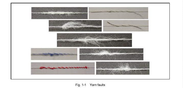
YARN FAULTS AND CLEARING:
It is still not possible to produce a yarn without faults for various reasons. Stickiness of cotton can contribute to the formation of thick and thin places. Fly liberation in Ringframe department is one of the major reasons for short faults in the yarn because of the fly gets spun into the yarn. Hence it is not possible to have fault free yarn from ringspinning, it is necessary to have yarn monitoring system in the last production process of the spinning mill. As physical principle for electronic yarn clearing the capacitive and the optical principle have established. Both principles have their advantages in specific applications.
Depending upon the rawmaterial, the machiery set up, production and process parameters, there are about 20 to 100 faults over a length of 100 km yarn which do not correspond to the deisred appearance of the yarn. This means that the yarn exhibits a yarn fault every 1 to 5 km. These faults are thick and thin faults, foregin fibres and diry places in the yarn.
The yarn faults which go into the woven or knitted fabric can be removed at very high costs or can not be removed at all. Therefore the yarn processing industry demands a fault free yarn.
The difference between frequent yarn faults and seldom occuring yarn faults are mainly given by the mass or diameter deviation and size. These faults are monitored by classimat or clearer installation on winding.
Each yarn contains, here and there, places which deviate to quite a considerable extent from the normal yarn corss-section. These can be short thick places, long thin places , long thick places or even spinners doubles. Eventhough such events seldom occur, they represent a potential disturbance in the appearance of the fabric or can negatively influnece subsequent processing of the yarn.
Short thick places are those faults which are not longer than approximately 8 cms, but have a cross-sectional size approx. twice that of the yarn. These faults are relatively frequent in all spun yarns. To an extent they are the result of the rawmaterial ( vegetable matter, non-seprated fibres, etc). To a much larger extent, these faults are produced in the spinning section of the mill and are the result of spun in fly. Short thick places are easily determinable in the yarn. In many cases, they cause disturbances in subsequent processing. Once they reach a certain size( cross-section and length) , and in each case accoridng to the type of yarn and its application, short thick place fults can considerably affect the appearance of the finished product.
Long thick places are much more seldom-occuring than the short thick places and usually have a length longer than 40cms. In some cases, their length can even reach many meters. Their cross sectional size approx. + 40% to +100% and more with respect of the mean cross-section of the yarn. Long thick places will affect the fabric apperance. Faults like spinners doubles are difficult to determine in the yarn, with the naked eye. On the other hand, they can produce quite fatal results in the finished product. A spinners double in the warp or in yarn for circular knitting can downgrade hundreds of meters of woven , or knitted fabric.
Thin places occur in two length groups. Short thin places are known as imperfections, and have a length approx. three times the mean staple length of the fibre. Their frequency is dependent on the rawmaterial and the setting of the drafting element. They are too frequent in the yarn to be extracted by means of the electronic yarn clearing.
Long thin places have lengths of approx. 40cms and longer and a cross-sectional decrease with respect to the mean yarn cross-section of approx.30 to 70%. They are relatively seldom-occuring in short staple yarns, but much more frequently-occuring in long staple yarns. Long thin faults are difficult to determine in the yarn by means of the naked eye. Their effect in the finished product however, can be extremely serious.
The quite extensive application of electronic yarn clearing has set new quality standards with respect to the number of faults in spun yarns.
It is therefore necessary to evolve a method of yarn fault classification before clearing the faults in winding. The most important aspect is certainly the determination of the fault dimensions of cross-sectional size and length. With such a cross-section and length classification and by means of the correct choice of the class limits, the characteristic dimensions of the various fault types can be taken into consideration, then a classification system will result which is suitable primarily for satisfying the requirements of yarn clearing and yet allows, to quite a large extent, for a selection of the various types of faults.
The yarn faults are classified according to their length and cross-sectional size, and this in 23 classes.
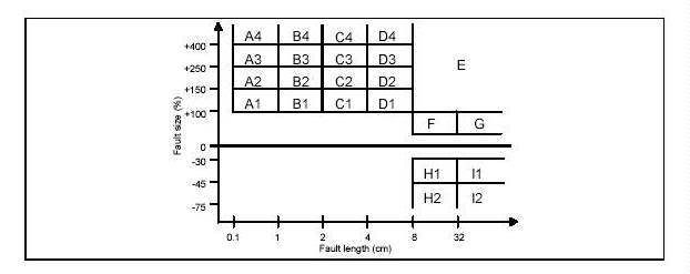
FIG: CLASSIMAT FAULTS:
- The cross-sectional deviations are given +% or -% values. i.e theupper limit, respectively , lower limit with respect to the mean yarn fault cross-section is measure in %. The fault length is measured in cms.
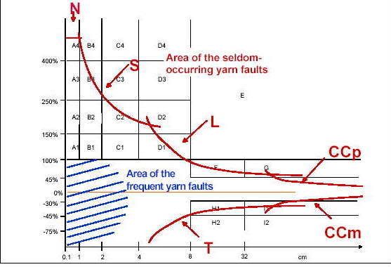
FIG: YARN CLEARING CONCEPT OF USTER QUANTUM CLEARER
N - NEPS
S- SHORT FAULTS
L-LONG FAULTS
CCP - COARSE COUNTS
CCM-FINE COUNTS
The classes and their limits are set out according to the following:
- Short thick place faults: 16 classes with the limits, 0.1 cm, 2cm, 4cm, and 8cm for the lengths and +100%, +150%,+250%, and +400% for the cross-sectional sizes are provided. The classes are indicated A1...D4. The classes A4, B4,C4,D4 contain all those faults, according to their length, whose cross-sectional size oversteps +400%.
- spinners doubles: This refers to a class (with the indication E) for faults whose length oversteps 8cms and whose cross-sectional size oversteps +100 ( open to the right and upwards)
- Long thick place faults and thick ends: The long thin place faults are contained in 4 classes with the limits 8 cms and 32 cms for the lengths, and -30% , -45% and -75% for the cross-sectional sizes. The classes are designated H1.....I2. The classes I1 and I2 are open to the right. i.e they contain all those thin places having a size between -30 and -45%, respetively, -45% and -75% and whose lengths are longer than 32 cms. The classification of the shorter thin places is of no advantage in the analysis of the seldom-occuring faults.
Types of Electronic Yarn Clearers
Electronic Yarn Clearers available in the market are principally of two types –capacitive and optical. Clearers working on the capacitive principle have ‘ mass’as the reference for performing its functions while optical clearers function with ‘ diameter’ as the reference. Both have their merits and demerits and are equally popular in the textile industry. Besides the above basic difference in measuring principle, the basis of functioning of both the types of clearers are similar if not exactly same. Since most of the other textile measurements like, U% / CV%, thick and thin places etc., in various departments take into account mass as the reference parameter, the functioning of the capacitive clearer is explained in some detail in the following sections.
Functioning Principle
The yarn is measured in a measuring field constituted by a set of parallely placed capacitor plates. When the yarn passes through this measuring field (between the capacitor plates), an electrical signal is produced which is proportional to the change in mass per unit length of the yarn. This signal is amplified and fed to the evaluation channels of the yarn clearing installation. The number and type of evaluation channels available are dependent on the sophistication and features of the model of the clearer in use. Each of the channels reacts to the signals for the corresponding type of yarn fault. When the mass per unit length of the yarn exceeds the threshold limit set for the channel, the cutting device of the yarn clearer cuts the yarn.
Yarn Clearer Settings
The yarn clearer has to be provided with certain basic information in order to obtain the expected results in terms of clearing objectionable faults. The following are some of them -
a. Clearing Limit:
The clearing limit defines the threshold level for the yarn faults, beyond which the cutter is activated to remove the yarn fault. The clearing limit consists of two setting parameters - Sensitivity and Reference Length.
i. Sensitivity - This determines the activating limit for the fault cross sectional size.
ii. Reference Length – This defines the length of the yarn over which the fault cross – section is to be measured. Both the above parameters can be set within a wide range of limits depending on specific yarn clearing requirements. Here, it is worth mentioning that the ‘ reference length’ may be lower or higher than the actual ‘ fault length’. For a yarn fault to be cut, the mean value of the yarn fault cross-section has to overstep the set sensitivity for the set reference length.
b. Yarn Count :
The setting of the yarn count provides a clearer with the basic information on the mean value of the material being processed to which the clearer compares the instantaneous yarn signals for identifying the seriousness of a fault.
c. Material Number:
Besides the yarn count there are certain other factors which influence the capacitance signal from the measuring field like type of fibre (Polyester / Cotton / Viscose etc.) and environmental conditions like relative humidity. These factors are taken into consideration in the ‘ Material Number’ . The material number values for different materials are provided in Table.
Table :material number
| 7.5 | cotton, wool, viscost | 8.5 very damp material (80%Rh) 6.5 very dry material(50% RH) |
| 6 | natural silk | 7 very damp material 5 very dry material |
| 5.5 | acetate, acrylonitrile polyamide | 50 to 80% RH 50 to 80% RH |
| 4.5 | polypropylene, poly ethylene | 50 to 80% RH |
| 3.5 | polyester | 50 to 80%RH |
| 2.5 | polyvinyl chloride | 50 to 80% RH |
From the values given in the table it could be seen that, for water absorbent fibres like cotton, the Material Number is changed by 1 for a 15% change in Relative Humidity. A reduction in material number results in a more sensitive setting causing higher fault removal. For blended yarns, the material number is formed from the sum of the percentage components of the blend. For instance, when a 67/33 Polyester / Cotton blend is run at an RH of 65%, the Material umber should be set at (0.67 * 3.5) + (0.33 * 7.5) = 4.8.
d. Winding Speed:
The setting of the winding speed is also very critical for accurate removal of faults. It is recommended that, instead of the machine speed, the delivery speed be set by actual calculation after running the yarn for 2-3 minutes and checking the length of yarn delivered. Setting a higher speed than the actual is likely to result in higher number of cuts. Similarly a lower speed setting relative to the actual causes less cuts with some faults escaping without being cut. In most of the modern day clearers, the count, material number and speeds are monitored and automatically corrected during actual running of the yarn.
Fault Channels:
The various fault channels available in a latest generation yarn clearer are as follows:
1. Short Thick places
2. Long Thick Places
3. Long Thin Places
4. Neps
5. Count
6. Splice
The availability of one or more of the above channels is dependent on the type of the yarn clearer. Most of the modern clearers have the above channels. Besides detection of the various types of faults, with latest clearers, it is also possible to detect concentration of faults in a specific length of yarn by means of alarms(cluster faults).
Contamination Clearing:
SPLICING:
A high degree of yarn quality is impossible through knot, as the knot itself is objectionable due to its physical dimension, appearance and problems during downstream processes. The knots are responsible for 30 to 60% of stoppages in weaving.
Splicing is the ultimate method to eliminate yarn faults and problems of knots and piecing. It is universally acceptable and functionally reliable. This is in spite of the fact that the tensile strength of the yarn with knot is superior to that of yarn with splice. Splicing is a technique of joining two yarn ends by intermingling the constituent fibres so that the joint is not significantly different in appearance and mechanical properties with respect to the parent yarn. The effectiveness of splicing is primarily dependent on the tensile strength and physical appearance.
Splicing satisfies the demand for knot free yarn joining: no thickening of the thread or only slight increase in its normal diameter, no great mass variation, visibly unobjectionable, no mechanical obstruction, high breaking strength close to that of the basic yarn under both static and dynamic loading, almost equal elasticity in the joint and basic yarn. No extraneous material is used and hence the dye affinity is unchanged at the joint. In addition, splicing enables a higher degree of yarn clearing to be obtained on the electronic yarn clearer.
Splicing technology has grown so rapidly in the recent past that automatic knotters on modern high speed winding machine are a thing of the past. Many techniques for splicing have been developed such as Electrostatic splicing, Mechanical splicing and Pneumatic splicing. Among them, pneumatic splicing is the most popular. Other methods have inherent drawbacks like limited fields of application, high cost of manufacturing, maintenance and operations, improper structure and properties of yarn produced.
Pneumatic Splicing
The first generation of splicing systems operated with just one stage without proceeding to trimming. The yarn ends were fed into the splicing chamber and pieced together in one operation. Short fibres, highly twisted and fine yarns could not be joined satisfactorily with such method. Latest methods of splicing process consist of two operations. During the first stage, the ends are untwisted, to achieve a near parallel arrangement of fibres. In a second operation the prepared ends are laid and twisted together.
Principle of Pneumatic Splicing
The splicing consists of untwisting and later re-twisting two yarn ends using air blast, i.e., first the yarn is opened, the fibres intermingled and later twisted in the same direction as that of the parent yarn. Splicing proceeds in two stages with two different air blasts of different intensity. The first air blast untwists and causes opening of the free ends. The untwisted fibres are then intermingled and twisted in the same direction as that of parent yarn by another air blast
Structure of Splice
Analysis of the longitudinal and transverse studies revealed that the structure of the splice comprises of three distinct regions/elements brought by wrapping, twisting and tucking / intermingling.
Wrapping :
The tail end of each yarn strand is tapered and terminates with few fibres. The tail end makes a good wrapping of several turns and thus prevents fraying of the splice. The fibres of the twisting yarn embrace the body of the yarn and thus acts as a belt. This in turn gives appearance to the splice.
Twisting
The two yarn ends comprising the splice are twisted around the body of the yarn, each yarn strand twists on the body of the yarn on either side of the middle of the splice. The cross-section of this region distinctly shows the fibres of the two yarn strands separately without any intermingling of the fibres.
Tucking / Intermingling
The middle portion of the splice is a region (2-5 mm) with no distinct order. The fibres from each yarn end intermingle in this splice zone just by tucking. The studies on quantitative contribution of splice elements showed that intermingling/tucking contributes the most to the strength of splice (52%), followed by twisting (33%) and wrapping (about 15%). The lower strength of the splice is attributed to the lower packing coefficient of the splice zone. Spliced yarn has a lower breaking elongation than normal yarn. Breaking elongation is mainly affected by intermingling. Wrapping and twisting provides mainly transverse forces. The absence of fibre migration gives lower breaking elongation to splice.
Effect of Variables on the Properties of the Spliced yarn
Several studies have been conducted on the effect of various variables on the properties of the spliced yarn.
Effect of Fibre Properties and Blend
Fibre properties such as torsional rigidity, breaking twist angle and coefficient of friction affect splice strength and appearance. The lower torsional rigidity and higher breaking twist angle permit better fibre intermingling. Higher coefficient of friction of fibres generates more inter-fibre friction to give a more cohesive yarn. Thus, these properties of fibre contribute to better retention of splice strength. In blended yarn, usually the addition of polyester to other fibre blend like P/W, P/C both for ring and rotor spun yarn increases splice strength.
Effect of Yarn Fineness
Several studies on cotton, polyester and wool report that coarser yarns have higher breaking strength but a moderate extension. The coarse yarn cross section contains more fibres and provides better fibre intermingling during pre-opening, hence the splice is stronger than that of finer yarns.
Effect of Yarn Twist
An increase in the twist significantly increases the breaking load and elongation, even at higher pneumatic pressure. This could be due to better opening of the strands at higher pneumatic pressure. Splicing of twisted ply yarn is more complicated than single yarn due to the yarn structure having opposing twists in the single and doubled yarns. Twisted yarns also require a relatively longer time for complete opening of the yarn ends.
Effect of Different Spinning Methods
Yarn produced with different spinning methods exhibit different structure and properties. Therefore, these yarns show significant differences in splice quality. The ring spun yarn lent best splicing but the potential of splicing is affected by the spinning conditions. The breaking strength percentage of ring spliced yarns to a parent yarn is 70% to 85% for cotton yarn. However, the breaking strength and extension of splice vary with fibre and yarn properties. Rotor spun yarns, due to the presence of wrapper fibres, make it difficult to untwist and the disordered structure is less ideal for splicing. The breaking strength retention varies from 54% to 71% and is much lower compared to the splice of ring spun yarns. In case of friction spun yarns, the highest relative tensile strength obtained at the spliced joints can be above 80%, but a number of splicing failures occurs due to unfavourable yarn structure. The air-jet-spun (MJS) yarn and the cover spun yarn are virtually impossible to splice. Only very low tensile strengths and elongation values can be attained due to the inadequate opening of the yarn ends during preparation of the splicing. The coefficient of variation of these properties is also generally high.
Effect of Opening Pressure
A study on 50/50 polyester cotton, 25 tex ring spun yarn shows a rise in tensile strength up to a certain opening pressure. However, long opening time deteriorates the strength. An increase in pressure up to 5 bar caused release of fibre tufts and fibre loss from the yarn ends in P/C blend which is due to intensive opening, but beyond this pressure, drafting and twisting in the opposite direction may also occur.
Effect of Splicing Duration
With a given splicing length, when the splicing is extended for a long period of time, the breaking strength of the spliced yarn and also their strength retention over the normal value of the basic yarn increases because of increased cohesive force resulting from an increased number of wrapping coils in a given length. The effects are more pronounced at higher splicing lengths. It is desirable however, that splicing duration be as short as possible. The splicing duration alone has no conclusive effect on elongation properties of splice yarn. It has also been observed that, for maximum splice strength, different materials require different durations of blast. These are between 0.5 to 1.8 seconds.
Effect of Splicing Length
Studies on splicing of flyer and wrap spun yarns spun with different materials, showed that regardless of the splicing material, the breaking strength and strength retention of both yarn types increase with the splicing length because of the increased binding length of the two yarn ends. Elongation at break and retention of elongation of both flyer and wrap spun spliced yarns increase with the splice length. Compared to the splicing duration, the splicing length has more pronounced effect on the load-elongation properties of the spliced yarn. It can be therefore be stated that the splices made on longer lengths and for longer period of time have more uniform strength.
Comparison of Dry and Wet Splicing
The comparative studies on dry and wet splicing with water showed that the breaking load retention for wet spliced yarns are significantly greater than dry spliced yarns. In fact, wet splicing is more effective for yarn made from long staple fibres and for coarse yarn. This may be due to higher packing coefficient resulting from wet splicing.
Effect of Splicing Chamber
The factors like method and mode of air supply and pressure along with type of prism affect the splicing quality. It was observed that irregular air pressure has advantages over constant pressure for better intermingling in the splicing chamber, which varies with different staple fibres, filament yarns, and yarns with S and Z twists. It is not possible to make a general comment regarding potential of the splicing chamber due to the multiplicity of factors influencing splicing.
Assessment of Yarn Splice Quality
The two important characteristics of a splice are appearance and strength. Although quality of splice can be assessed by methods like load-elongation, work of rupture, % increase in diameter and evaluation of its performance in down stream process etc., the appearance can be assessed either by simple visual assessment or by comparing with photograph of standard splice.
CHARACTERISTICS OF BOBBIN FORMATION:
- Strectch length: It is the length of the yarn deposited on the bobbin tube during each chase (one up and down movement of ringrail ) of ring rail. The length should be around 3.5 to 5 meters. It should be shorter for coarser yarns and longer for fine yarns.
- Winding ratio:It is the ratio of the length of yarn wound during the upward movement of the ring rail and the length wound during the downward movement of the ringrail.
- Bobbin taper: The ratio of the length of the upper taper of the cop (bobbin with yarn) to the diameter of the bobbin must be 1:2 or greater.
WINDING SPEED: It depends upon the following factors
- count
- type of yarn, (type of fibre, average strength and minimum strength)
- type and charactersitics of bobbin
- package taper
- final use of package
The best winding speed is the speed which allows the highest level of production possible for a given type of yarn and type of package, and with no damage whatsoever to the yarn.(abrasion and breaks due to excessive tension)
WINDING PRODUCTION: It depends upon the following factors
- winding speed
- time required by the machine to carry out one splicing operation
- bobbin length per bobbin( both bobbin weight and tpi to be considered, because TPI will affect the bobbin length). This decides the number of bobbin changes
- the number of faults in the yarn and the clearer settings, this decides the clearer cuts
- count
- the number of doffs. It depends upon the doff weight. Higher the doff weight, lower the number of doffs
- the time taken for each doff either by the doffer or by an operator
- Down time due to red light. It depends upon, number of red lights, number of repeaters setting for red lights, clearer settings like off count channel, cluster setting which will result in red lights and others
- bobbin rejections, it depends on weak yarn, wrong gaiting, double gaiting, bobbin characteritics etc.
WINDING PACKAGE DEFECTS: Following are some of the package defects which will result in complaints
- Yarn waste in the cones. This is due to loose yarn ends that are wound on to the cone
- Stitch, drop over, web: Yarn is visible on the small or on the big side of the cone either across the side , around the tube, or going back in the cone
- Damaged edges or broken ends on the cone: The yarn is broken on the edges or in the middle of the cone.
- Ring formation: The yarn runs in belt formation on to the package, because it is misguided
- Without transfer tail: The desired transfer tail is missing or too short
- Ribbon formation: Pattern or ring formation are made by the drum when rpm are stying the same
- Displaced yarn layers: yarn layers are disturbed and are sliding towards the small diameter of the cone
- Misguided yarn : The yarn is not equally guided over the hole package
- Cauliflower: On the smaller side of the package, the yarn shows a wrinkle effect
- Soft and Hard yarn layer: Some layer of yarn are pushed out on the small side of the cone
- Soft and Hard cones: Great difference in package density from one winder head to another