ALTERNATING CURRENT (AC):
The supply of current for electrical devices may come from a direct current source (DC), or an alternating current source(AC).In direct current electricity, electrons flow continuously in one direction from the source of power through a conductor to a load and back to the source of power. The voltage indirect current remains constant. DC power sources include batteries and DC generators. In alternating current an AC generator is used to make electrons flow first in one directionthen in another. Another name for an AC generator is analternator. The AC generator reverses terminal polarity manytimes a second. Electrons will flow through a conductor from the negative terminal to the positive terminal, first in onedirection then another.
AC SINE WAVE:
Alternating voltage and current vary continuously.The graphic representation for AC is a sine wave. A sine wave can represent current or voltage. There are two axes. The vertical axis represents the direction and magnitude of currentor voltage. The horizontal axis represents time.
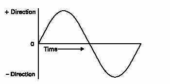
When the waveform is above the time axis, current is flowing in one direction. This is referred to as the positive direction.When the waveform is below the time axis, current is flowing in the opposite direction. This is referred to as the negative direction. A sine wave moves through a complete rotation of 360 degrees, which is referred to as one cycle. Alternating current goes through many of these cycles each second.The unit of measurement of cycles per second is hertz. In general it is 50Hz or 60 Hz depending upon the country.
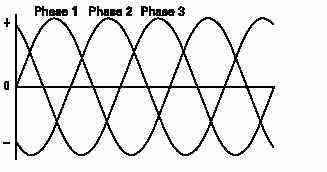
SINGLE PHASE AND THREE PHASE AC POWER:
Alternating current is divided into single-phase and threephase types. Single-phase power is used for small electical demands such as found in the home. Three-phase power is used where large blocks of power are required, such as found in commercial applications and industrial plants. Single-phasepower is shown in the above illustration. Three-phase power,as shown in the following illustration, is a continuous series of three overlapping AC cycles. Each wave represents a phase, and is offset by 120 electrical degrees.
AC GENERATORS:
BASIC GENERATOR:
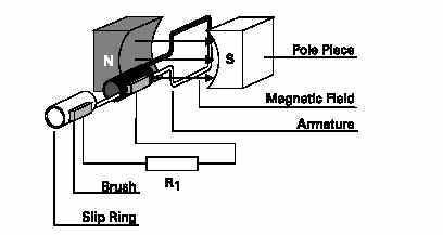
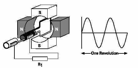
A basic generator consists of a magnetic field, an armature,slip rings, brushes and a resistive load. The magnetic field is usually an electromagnet. An armature is any number of conductive wires wound in loops which rotates through the magnetic field. For simplicity, one loop is shown. When aconductor is moved through a magnetic field, a voltage is induced in the conductor. As the armature rotates through the magnetic field, a voltage is generated in the armature which causes current to flow. Slip rings are attached to thearmature and rotate with it. Carbon brushes ride against the slip rings to conduct current from the armature to a resistive load.
BASIC GENERATION OPERATION:
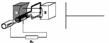
An armature rotates through the magnetic field. At an initial position of zero degrees, the armature conductors are moving parallel to the magnetic field and not cutting through any magnetic lines of flux. No voltage is induced.
GENERATION OPERATION FROM 0 TO 90 DEGREES:
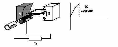
The armature rotates from zero to 90 degrees. The conductors cut through more and more lines of flux, building up to a maximum induced voltage in the positive direction.
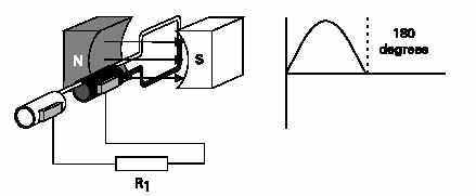
GENERATION OPERATION FROM 90 TO 180 DEGREES:
The armature continues to rotate from 90 to 180 degrees,cutting less lines of flux. The induced voltage decreases froma maximum positive value to zero.
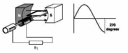
GENERATION OPERATION FROM 180 TO 270 DEGREES:
The armature continues to rotate from 180 degrees to 270degrees. The conductors cut more and more lines of flux, butin the opposite direction. Voltage is induced in the negativedirection building up to a maximum at 270 degrees.
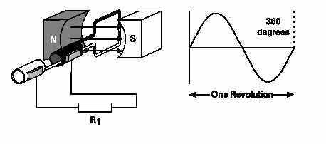
GENERATION OPERATION FROM 270 TO 360 DEGREES:
The armature continues to rotate from 270 to 360 degrees.Induced voltage decreases from a maximum negative valueto zero. This completes one cycle. The armature will continueto rotate at a constant speed. The cycle will continuouslyrepeat as long as the armature rotates.
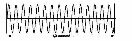
FREQUENCY:
The number of cycles per second made by voltage induced in the armature is the frequency of the generator. If the armature rotates at a speed of 60 revolutions per second, the generated voltage will be 60 cycles per second. The accepted term for cycles per second is hertz. The standard frequency in theUnited States is 60 hertz. The following illustration shows 15 cycles in 1/4 second which is equivalent to 60 cycles in onesecond.
FOUR POLE AC GENERATOR:
The frequency is the same as the number of rotations per second if the magnetic field is produced by only two poles.An increase in the number of poles, would cause an increase in the number of cycles completed in a revolution. A two-pole generator would complete one cycle per revolution and a four-pole generator would complete two cycles per revolution.An ACgenerator produces one cycle per revolution for each pair of poles.
VOLTAGE AND CURRENT:
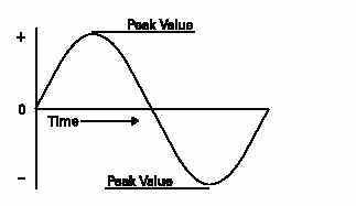
PEAK VALUE:
The sine wave illustrates how voltage and current in an ACcircuit rises and falls with time. The peak value of a sine waveoccurs twice each cycle, once at the positive maximum valueand once at the negative maximum value.
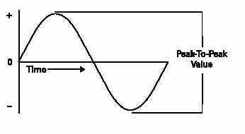
PEAK TO PEAK VALUE:
The value of the voltage or current between the peak positiveand peak negative values is called the peak-to-peak value.
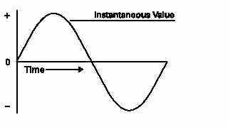
The instantaneous value is the value at any one particulartime. It can be in the range of anywhere from zero to thepeak value.
CALCULATING INSTANTANEOUS VOLTAGE:
The voltage waveform produced as the armature rotatesthrough 360 degrees rotation is called a sine wavebecauseinstantaneous voltage is related to the trigonometric functioncalled sine (sin q = sine of the angle). The sine curve representsa graph of the following equation:
e Epeak = ´sin q
Instantaneous voltage is equal to the peak voltage times thesine of the angle of the generator armature. The sine value isobtained from trigonometric tables. The following table reflectsa few angles and their sine value.
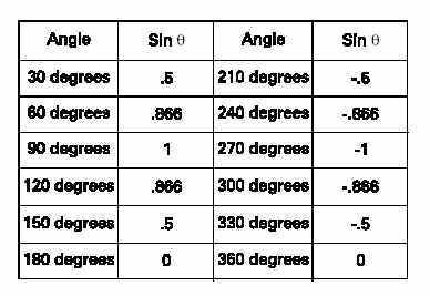
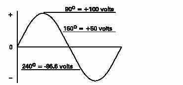
The following example illustrates instantaneous values at 90,150, and 240 degrees. The peak voltage is equal to 100 volts.By substituting the sine at the instantaneous angle value, theinstantaneous voltage can be calculated.
EFFECTIVE VALUE OF AN AC SINE WAVE:
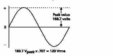
Alternating voltage and current are constantly changingvalues. A method of translating the varying values into anequivalent constant value is needed. The effective value ofvoltage and current is the common method of expressing thevalue of AC. This is also known as the RMS (root-meansquare)value. If the voltage in the average home is said to be120 volts, this is the RMS value. The effective value figuresout to be 0.707 times the peak value.
The effective value of AC is defined in terms of an equivalentheating effect when compared to DC. One RMS ampere ofcurrent flowing through a resistance will produce heat at thesame rate as a DC ampere.For purpose of circuit design, the peak value may also beneeded. For example, insulation must be designed to withstandthe peak value, not just the effective value. It may bethat only the effective value is known. To calculate the peakvalue, multiply the effective value by 1.41. For example, if theeffective value is 100 volts, the peak value is 141 volts.
INDUCTANCE:
The circuits studied to this point have been resistive. Resistance and voltage are not the only circuit properties that effect current flow, however. Inductance is the property of an electric circuit that opposes any change in electric current.Resistance opposes current flow, inductance opposes change in current flow. Inductance is designated by the letter "L". The unit of measurement for inductance is the henry (h).
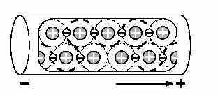
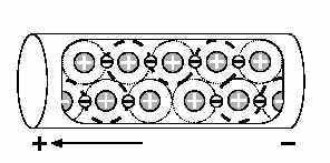
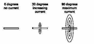
CURRENT FLOW AND FIELD STRENGTH:
Current flow produces a magnetic field in a conductor. The amount of current determines the strength of the magnetic field. As current flow increases, field strength increases, and as current flow decrease, field strength decreases.
Any change in current causes a corresponding change in the magnetic field surrounding the conductor. Current is constant in DC, except when the circuit is turned on and off, or when there is a load change. Current is constantly changing in AC,so inductance is a continual factor. A change in the magnetic field surrounding the conductor induces a voltage in the conductor. This self-induced voltage opposes the change in current. This is known as counter emf. This opposition causes a delay in the time it takes current to attain its new steady value. If current increases, inductance tries to hold it down. If current decreases, inductance tries to hold it up. Inductance is somewhat like mechanical inertia, which must be overcome to get a mechanical object moving, or to stop a mechanical object from moving. A vehicle, for example, takes a few moments to accelerate to a desired speed, or decelerate to a stop.
INDUCTORS:
Inductance is usually indicated symbolically on an electricaldrawing by one of two ways. A curled line or a filled rectanglecan be used.
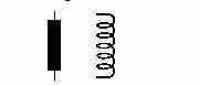
Inductors are coils of wire. They may be wrapped around a core. The inductance of a coil is determined by the number of turns in the coil, the spacing between the turns, the coil diameter, the core material, the number of layers of windings,the type of winding, and the shape of the coil. Examples of inductors are transformers, chokes, and motors.
SIMPLE INDUCTIVE CIRCUIT:
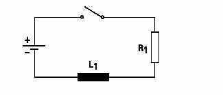
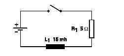
In a resistive circuit, current change is considered instantaneous.If an inductor is used, the current does not change asquickly. In the following circuit, initially the switch is openand there is no current flow. When the switch is closed,current will rise rapidly at first, then more slowly as the maximumvalue is approached. For the purpose of explanation, aDC circuit is used.
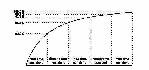
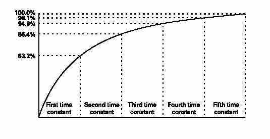
The time required for the current to rise to its maximum value is determined by the ratio of inductance, in henrys, to resistance, in ohms. This ratio is called the time constant of the inductive circuit. A time constant is the time, in seconds,required for the circuit current to rise to 63.2% of its maximum value. When the switch is closed in the previous circuit,current will begin to flow. During the first time constant current rises to 63.2% of its maximum value. During thesecond time constant, current rises to 63.2% of the remaining 36.8%, or a total of 86.4%. It takes about five time constants for current to reach its maximum value.
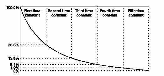
Similarly, when the switch is opened, it will take five timeconstants for current to reach zero. It can be seen that inductanceis an important factor in AC circuits. If the frequency is60 hertz, current will rise and fall from its peak value to zero120 times a second.
CALCULATING THE TIME CONSTANT OF AN INDUCTIVE CIRCUIT:
The time constant is designated by the symbol ìtî. To determinethe time constant of an inductive circuit use one of thefollowing formulas:
T( in seconds) = L(henrys) / R (ohms)
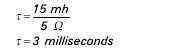
T(in milliseconds) = L(millihenrys)/ R(ohms)
In the following illustration, L1 is equal to 15 millihenrys andR1 is equal to 5 W. When the switch is closed, it will take 3milliseconds for current to rise from zero to 63.2% of itsmaximum value.
FORMULA FOR SERIES INDUCTORS:
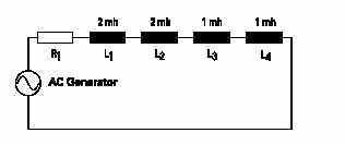
Lt = L1+L2+L3+L4
Lt = 2mh+2mh+1mh+1mh = 6mh
FORMULA FOR PARALLEL INDUCTORS:
In the following circuit, an AC generator is used to supplyelectrical power to three inductors. Total inductance is calculatedusing the following formula:
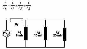
1/Lt = 1/5 + 1.10 + 1/20 = 7/20
Lt = 2.86 mh
CAPACITANCE:
CAPACITANCE AND CAPACITORS:
Capacitance is a measure of a circuitís ability to store an electrical charge. A device manufactured to have a specific amount of capacitance is called a capacitor. A capacitor is made up of a pair of conductive plates separated by a thin layer of insulating material. Another name for the insulating material is dielectric material. When a voltage is applied to the plates, electrons are forced onto one plate. That plate has an excess of electronswhile the other plate has a deficiency of electrons. The plate with an excess of electrons is negatively charged. The plate with a deficiency of electrons is positively charged.
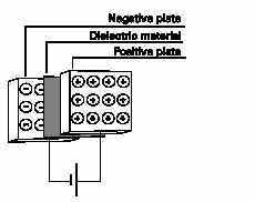
Direct current cannot flow through the dielectric material because it is an insulator. Capacitors have a capacity to hold aspecific quantity of electrons. The capacitance of a capacitor depends on the area of the plates, the distance between theplates, and the material of the dielectric. The unit of measurement for capacitance is farads, abbreviated "F". Capacitors usually are rated in mF (microfarads), or pF (picofarads).
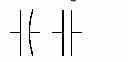
CAPACITOR CIRCUIT SYMBOLS
Capacitance is usually indicated symbolically on an electricaldrawing by a combination of a straight line with a curved line,or two straight lines.
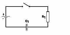
SIMPLE CAPACITIVE CIRCUIT:
In a resistive circuit, voltage change is considered instantaneous.If a capacitor is used, the voltage across the capacitor does not change as quickly. In the following circuit, initially the switch is open and no voltage is applied to the capacitor.When the switch is closed, voltage across the capacitor will rise rapidly at first, then more slowly as the maximum value is approached. For the purpose of explanation, a DC circuit isused.
CAPACITIVE TIME CONSTANT
The time required for voltage to rise to its maximum value in a circuit containing capacitance is determined by the product of capacitance, in farads, times resistance, in ohms. This is the time it takes a capacitor to become fully charged. This product is the time constant of a capacitive circuit. The time constant gives the time in seconds required for voltage across the capacitor to reach 63.2% of its maximum value. When the switch is closed in the previous circuit, voltage will be applied.During the first time constant, voltage will rise to 63.2% of its maximum value. During the second time constant,voltage will rise to63.2% of the remaining 36.8%, or a total of 86.4%. It takes about five time constants for voltage across the capacitor to reach its maximum value.

Similarly, during this same time, it will take five time constants for current through the resistor to reach zero.
CALCULATING THE TIME CONSTANT OF A CAPACITIVE CIRCUIT:
Time constant is decided by the symbol "T".To determine the time constant of a capacitive circuit, use oneof the following formulas:
T(in seconds) = R(megohms) X C(microfarads)
T(in microseconds) = R(megohms) X C(pico farads)
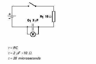
T(in microseconds) = R(ohms) X C (microfarads)
In the following illustration, C1 is equal to 2 mF, and R1 is equalto 10 W. When the switch is closed, it will take20microseconds for voltage across the capacitor to risefrom zero to 63.2% of its maximum value. There are fivetime constants, so it will take 100 microseconds for this voltageto rise to its maximum value.
FORMULA FOR SERIES CAPACITORS:
Connecting capacitors in series decreases total capacitance.The effect is like increasing the space between the plates. Therules for parallel resistance apply to series capacitance. In thefollowing circuit, an AC generator supplies electrical power tothree capacitors. Total capacitance is calculated using thefollowing formula:
1/Ct = 1/C1+1/C2+1/C3
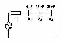
1/Ct = 1/5+1/10+1/20 = 7/20 = 2.86
FORMULA FOR PARALLES CAPACITORS:
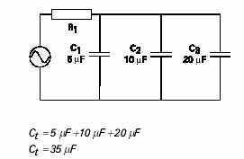
In the following circuit, an AC generator is used to supplyelectrical power to three capacitors. Total capacitance is calculatedusing the following formula:
Ct = C1+C2+C3
INDUCTIVE AND CAPACITANCE REACTANCE:
In a purely resistive AC circuit, opposition to current flow is called resistance. In an AC circuit containing only inductance,capacitance, or both, opposition to current flow is called reactance. Total opposition to current flow in an AC circuit that contains both reactance and resistance is called impedance designated by the symbol Z. Reactance and impedance are expressed in ohms.
INDUCTIVE REACTANCE:
Inductance only affects current flow when the current is changing. Inductance produces a self-induced voltage(counter emf) that opposes changes in current. In an ACcircuit, current is changing constantly. Inductance in an AC circuit, therefore, causes a continual opposition. This opposition to current flow is called inductive reactance, and is designated by the symbol XL. Inductive reactance is dependent on the amount of inductance and frequency. If frequency is low current has more time to reach a higher value before the polarity of the sine wave reverses. If frequency is high current has less time to reach a higher value. In the following illustration, voltage remains constant. Current rises to a higher value at a lower frequency than a higher frequency.
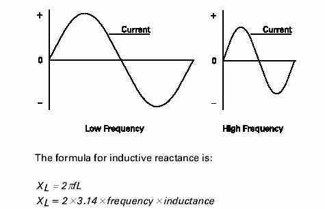
In a 60 hertz, 10 volt circuit containing a 10 mh inductor, the inductive reactance would be:
Xl = 2 x 3.14 x 60 x .010 = 3.768 ohms
Once inductive reactance is known, Ohmís Law can be usedto calculate reactive current.
I = E/Z = 10/3.768 = 2.65 amps
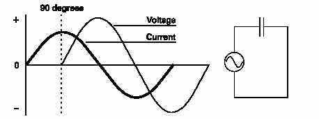
PHASE RELATIONSHIP BETWEEN CURRENT AND VOLTAGE IN AN INDUCTIVE CIRCUIT:
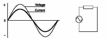
Current does not rise at the same time as the source voltage in an inductive circuit. Current is delayed depending on the mount of inductance. In a purely resistive circuit, current and voltage rise and fall at the same time. They are said to be ìinphase.î In this circuit there is no inductance, resistance andimpedance are the same.
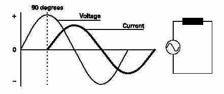
In a purely inductive circuit, current lags behind voltage by 90 degrees. Current and voltage are said to be "out of phase". In this circuit, impedance and inductive reactance are the same.
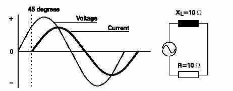
All inductive circuits have some amount of resistance. AC current will lag somewhere between a purely resistive circuit,and a purely inductive circuit. The exact amount of lag depends on the ratio of resistance and inductive reactance. The more resistive a circuit is, the closer it is to being in phase.The more inductive a circuit is, the more out of phase it is. In the following illustration, resistance and inductive reactance are equal. Current lags voltage by 45 degrees.
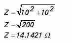
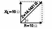
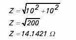
When working with a circuit containing elements of inductance,capacitance, and resistance, impedance must becalculated. Because electrical concepts deal with trigonometric functions, this is not a simple matter of subtraction and addition.
![]()
In the circuit illustrated above, resistance and inductive reactance are each 10 ohms. Impedance is 14.1421 ohms. A simple application of Ohmís Law can be used to find total circuit current.
VECTORS:
Another way to represent this is with a vector. A vector is a graphic representation of a quantity that has direction and 50 miles southwest from another. The magnitude is 50 miles,and the direction is southwest. Vectors are also used to show electrical relationships. As mentioned earlier, impedance (Z) is the total oppositon to current flow in an AC circuit containing resistance, inductance, and capacitance. The following vector illustrates the relationship between resistance and inductive reactance of a circuit containing equal values of each. The angle between the vectors is the phase angle represented by the symbol q. When inductive reactance is equal to resistance the resultant angle is 45 degrees. It is this angle that determines how much current will lag voltage.
CAPACITANCE REACTANCE:
Capacitance also opposes AC current flow. Capacitive reactance is designated by the symbol XC. The larger the capacitor,the smaller the capacitive reactance. Current flow in a capacitive AC circuit is also dependent on frequency. Thefollowing formula is used to calculate capacitive reactance:
Xc = 1/2 x 3.14 x f x C
Capacitive reactance is equal to 1 divided by 2 times pi, times the frequency, times the capacitance. In a 60 hertz, 10 volt circuit containing a 10 microfarad capacitor the capacitivereactance would be:
Xc = 1/2 x 3.14 x f x C = 1/(2 x 3.14 x 60 x 0.000010) = 265.39 ohms
Once capacitive reactance is known, Ohmís Law can be used to calculate reactive current.
I = E/Z = 10/ 265.39 = 0.0376 amps
PHASE RELATIONSHIP BETWEEN CURRENT AND VOLTAGE IN AN CAPACITIVE CIRCUIT:
The phase relationship between current and voltage are opposite to the phase relationship of an inductive circuit. In a purely capacitive circuit, current leads voltage by 90 degrees.All capacitive circuits have some amount of resistance. AC current will lead somewhere between a purely resistive circuit and a purely capacitive circuit. The exact amount of lead depends on the ratio of resistance and capacitive reactance.The more resistive a circuit is, the closer it is to being in phase. The more capacitive a circuit is, the more out of phase it is. In the following illustration, resistance and capacitive reactance are equal. Current leads voltage by45 degrees.
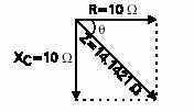
CALCULATING IMPEDENCE IN A CAPACITIVE CIRCUIT:
The following formula is used to calculate impedence in a capacitive circuit
![]()
In the cirucuit illustrated above, resistance and capacitivef reactance are each 10 ohms. Impedence is 14.1421 ohms.
The following vector illustrates the relationship betweenresistance and capacitive reactance of a circuit containingequal values of each. The angle between the vectors is thephase angle represented by the symbol q. When capacitivereactance is equal to resistance the resultant angle is -45degrees. It is this angle that determines how much currentwill lead voltage.