A case study of Power quality improvement and energy saving in textile industry using solid state harmonic filter
M.K.Pradhan, Kamlesh Keharia, Rajesh Darapu, B. Mariappan
pradhan@emcoindia.com; krkeharia@emcoindia.com; rdarapu@emcoindia.com; bmariappan@emcoindia.com
R & D Department, EMCO Limited, Thane, India
Abstract - This paper presents a case study of application of solid-state harmonic filter to improve electric power quality and reduce energy consumption in textile industries. Detailed studies were carried out in various textile firms in India and the effects of poor power quality specially harmonics were analyzed on the productivity and energy consumption. Harmonic current generated by nonlinear loads like motors driven by Variable Frequency Drives (VFD) cause power system heating and add to user power bills. The harmonic related losses are present in the power cables, bus bars linking the loads with source, the power transformer itself. A more serious effect of harmonic loads served by transformer is due to an increase in winding eddy current losses. The heat generated due to harmonics must be removed in order to save electrical energy, thus leading to savings in the utility bill.
The paper is a case study where a 1.5 MVA transformer used for powering the spinning section of a textile mill. The current harmonics is recorded with & without using the Active harmonic filter (AHF). The power parameters are recorded on both the primary & secondary side of transformer to demonstrate how the active harmonic filter can reduce the effects of harmonics and save energy.
I. Introduction
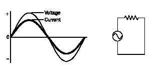
Machineries which draw non sinusoidal currents when a sinusoidal voltage is applied create harmonics. These harmonics are multiple of the fundamental frequency of an electrical power system. Machineries used in a plant that draw non sinusoidal currents are also known as non linear load. Listed below are some of these devices.
1) Adjustable speed drives
2) DC Drives
3) Variable frequency drives
4) 6 pulse converters
5) Power rectifiers
6) Uninterrupted Power Supplies
7) Computers
If a facility has more than 15% non linear load, then a harmonic study should be performed before applying the Power Quality (PQ) solutions. Various methods are used in order to promote the savings involved with applying PQ solutions. The most important method followed in Textile mills is to claim significant benefits associated with the cost of solution equipment related to payback. Many are so called tangible or hard savings but many are intangible or related to payback. Many are so called tangible or hard savings but many are intangible or soft savings that are associated with or a side benefit of the solution.
Hard savings include:
· Reduced energy (kWH) usage Demand reduction (kVA)
· Improved PF & voltage quality.
· Reduction in I2R losses in conductor
· Reduction in equipment losses (motors, transformers,
switchyard )
· Operating cost reduction
· Reduction in taxes
Soft savings include:
· Reactive power savings (kVAR)
· Apparent power savings (kVA)
· Increased electrical equipment life.
· Improved performance of equipment
· Protection of sensitive electronic equipment.
· Reduced maintenance, decrease consumption of
spare parts
· Space savings
· Better capacity utilization of transformer & generator
· Less Heating ventilation & Air conditioning (HVAC)
system
The hard savings are the direct financial benefits to the purchasing company. Each electrical parameter that contributes to hard saving must be assessed, monitored & measured accurately to claim the appropriate payback period.
II. Problems observed in textile industries
Power system apparatus overheating:
It is normally observed that transformer gets overheated. Extra fans near transformers and at places water sprinkler are installed to cool the transformers. LT distribution panel doors are kept open and cooling fans and even air conditioning of panel room is carried out to cool the switchgears, busbars in the room. The bursting of PF capacitors due to excessive harmonics was reported. Over correction of PF leading to increase of LT voltage has damaged the sensitive components of VFD used in machineries.
Detailed harmonic measurement study on presence of harmonics and their effects on more than 20 textile industries have been carried out. Following table shows the %THD content present at the PCC of various machineries.
The heating of power transformer in the presence of harmonics is analyzed. The theoretical calculations of heat loss along with the measurement were carried out.
K-factor is the ratio of eddy current losses due to distorted current compared to the losses for the same rms fundamental frequency current.
The K factor is represented by,


III. Harmonic related (kWH) losses in transformer Two main component areas to get maximum reduction in energy in a plant are
A. The power transformer supporting harmonic loads
B. The cables carrying power to the harmonic load
A) Power Transformer:-
The transformer loss is divided in to two components:-
a. No Load loss
b. Load related loss
The load losses are further divided in to two parts that are I2R losses (PR), the ohmic losses & stray losses. The stray losses are caused by eddy currents that produce stray electromagnetic flux in the windings, core, core clamps, magnetic shields, tank walls & other structural parts. For a transformer feeding harmonic producing loads, the eddy current loss in the windings may be the most dominant loss component in the transformer.
For non sinusoidal load currents, the I2R Power loss (PR) can be obtained by the sum of the squares of the fundamental and harmonic currents as shown in below equation.
The K–factor determines the capability of a transformer to handle harmonics loads. By providing additional capacity ( large-size or multiple winding conductors), K- factor rated transformers are capable of safely withstanding additional winding eddy current losses equal to K times the rated eddy current loss.
Per unit losses:
Since the greatest concern under harmonic load conditions will be for over-heating of the windings, it is convenient to consider loss density in the windings on a per unit basis. (Base current is rated current & base loss density is the I2R loss density at rated current in watts per kg of conductor). Now the transformer loss which is


IV.Case study- 1.5MVA Transformer in the textile mill. The transformer in the case study is loaded at 70 % of its 1500 kVA rating. Each phase is loaded at 350 KW and Irms is 1487 Amp. At this point the load is compensated, (that is, unity power factor & no harmonics). The objective here is to calculate the additional losses caused by harmonics in the load current after finding out the K- factor.
Fig.1-A, Fig.1-B and Fig.1-C show the secondary current waveform, the current harmonic Table & the Power & energy data.


Table -2 shows the secondary harmonic current and Ih is the rms current of hth harmonic current, and I1 is the rms value of the fundamental current. Total Current THD of 13.3% is taken into calculation. K-factor is calculated using Equation -3 & it is 1.483 (summation of last row in Table-2).
The eddy current losses will increase by 1.483 times due to harmonic current in the transformer.
For the transformer used in case study the PEC-R is taken from the transformer test record. It is 1221 watts.
All of the stray loss is assumed to be winding eddy current loss. The division of eddy current loss between the windings is assumed to be as 70% in the inner winding and 30% in the outer winding of the transformer. Since the transformer turns ratio exceeds 4:1 & the secondary current exceeds 1000 amps, the secondary winding eddy current loss is 0.7 times PEC-R [ref-1]. Eddy current loss distribution within each winding is assumed to be nonuniform. The maximum eddy current loss density is assumed to be in the region of the winding hottest spot and is assumed to be 400% of the average eddy current loss density for that winding. Taking the assumptions in to account,


The tested load loss given by the transformer manufacturer is 13.265 kW.
Therefore the additional losses calculated due to harmonic current flowing through transformer is (13.265 x 0.54) =7.16 kW.
This additional loss can easily be mitigated by using a PQ solution gadget such as ACTIVE HARMONIC FILTER. Here the loss of 7.16 kW is less than 0.5% of the full load capability of the transformer.
Hence a high accuracy (below 0.5% class accuracy) revenue grade meter, CT s and PTs are required to measure the decrease in losses in transformer with Active harmonic filters in operation.
V. Experimental details of field test
200 Amp (2x100) EMCOSINE Active Harmonic filter was installed in power distribution board, PDB 2 feeder of spinning unit supplied by 1.5 MVA transformer- TX1. This transformer also supports other linear loads in addition to the VFD loads connected to PDB 2.
We could measure high current harmonics giving more than 30% of THD in PDB2.The readings were recorded to see the improvement achieved by eliminating the harmonics in the feeder line leading

Read more...
M.K.Pradhan, Kamlesh Keharia, Rajesh Darapu, B. Mariappan
pradhan@emcoindia.com; krkeharia@emcoindia.com; rdarapu@emcoindia.com; bmariappan@emcoindia.com
R & D Department, EMCO Limited, Thane, India
Abstract - This paper presents a case study of application of solid-state harmonic filter to improve electric power quality and reduce energy consumption in textile industries. Detailed studies were carried out in various textile firms in India and the effects of poor power quality specially harmonics were analyzed on the productivity and energy consumption. Harmonic current generated by nonlinear loads like motors driven by Variable Frequency Drives (VFD) cause power system heating and add to user power bills. The harmonic related losses are present in the power cables, bus bars linking the loads with source, the power transformer itself. A more serious effect of harmonic loads served by transformer is due to an increase in winding eddy current losses. The heat generated due to harmonics must be removed in order to save electrical energy, thus leading to savings in the utility bill.
The paper is a case study where a 1.5 MVA transformer used for powering the spinning section of a textile mill. The current harmonics is recorded with & without using the Active harmonic filter (AHF). The power parameters are recorded on both the primary & secondary side of transformer to demonstrate how the active harmonic filter can reduce the effects of harmonics and save energy.
I. Introduction
Machineries which draw non sinusoidal currents when a sinusoidal voltage is applied create harmonics. These harmonics are multiple of the fundamental frequency of an electrical power system. Machineries used in a plant that draw non sinusoidal currents are also known as non linear load. Listed below are some of these devices.
1) Adjustable speed drives
2) DC Drives
3) Variable frequency drives
4) 6 pulse converters
5) Power rectifiers
6) Uninterrupted Power Supplies
7) Computers
If a facility has more than 15% non linear load, then a harmonic study should be performed before applying the Power Quality (PQ) solutions. Various methods are used in order to promote the savings involved with applying PQ solutions. The most important method followed in Textile mills is to claim significant benefits associated with the cost of solution equipment related to payback. Many are so called tangible or hard savings but many are intangible or related to payback. Many are so called tangible or hard savings but many are intangible or soft savings that are associated with or a side benefit of the solution.
Hard savings include:
· Reduced energy (kWH) usage Demand reduction (kVA)
· Improved PF & voltage quality.
· Reduction in I2R losses in conductor
· Reduction in equipment losses (motors, transformers,
switchyard )
· Operating cost reduction
· Reduction in taxes
Soft savings include:
· Reactive power savings (kVAR)
· Apparent power savings (kVA)
· Increased electrical equipment life.
· Improved performance of equipment
· Protection of sensitive electronic equipment.
· Reduced maintenance, decrease consumption of
spare parts
· Space savings
· Better capacity utilization of transformer & generator
· Less Heating ventilation & Air conditioning (HVAC)
system
The hard savings are the direct financial benefits to the purchasing company. Each electrical parameter that contributes to hard saving must be assessed, monitored & measured accurately to claim the appropriate payback period.
II. Problems observed in textile industries
Power system apparatus overheating:
It is normally observed that transformer gets overheated. Extra fans near transformers and at places water sprinkler are installed to cool the transformers. LT distribution panel doors are kept open and cooling fans and even air conditioning of panel room is carried out to cool the switchgears, busbars in the room. The bursting of PF capacitors due to excessive harmonics was reported. Over correction of PF leading to increase of LT voltage has damaged the sensitive components of VFD used in machineries.
Detailed harmonic measurement study on presence of harmonics and their effects on more than 20 textile industries have been carried out. Following table shows the %THD content present at the PCC of various machineries.
The heating of power transformer in the presence of harmonics is analyzed. The theoretical calculations of heat loss along with the measurement were carried out.
K-factor is the ratio of eddy current losses due to distorted current compared to the losses for the same rms fundamental frequency current.
The K factor is represented by,
III. Harmonic related (kWH) losses in transformer Two main component areas to get maximum reduction in energy in a plant are
A. The power transformer supporting harmonic loads
B. The cables carrying power to the harmonic load
A) Power Transformer:-
The transformer loss is divided in to two components:-
a. No Load loss
b. Load related loss
The load losses are further divided in to two parts that are I2R losses (PR), the ohmic losses & stray losses. The stray losses are caused by eddy currents that produce stray electromagnetic flux in the windings, core, core clamps, magnetic shields, tank walls & other structural parts. For a transformer feeding harmonic producing loads, the eddy current loss in the windings may be the most dominant loss component in the transformer.
For non sinusoidal load currents, the I2R Power loss (PR) can be obtained by the sum of the squares of the fundamental and harmonic currents as shown in below equation.
Per unit losses:
Since the greatest concern under harmonic load conditions will be for over-heating of the windings, it is convenient to consider loss density in the windings on a per unit basis. (Base current is rated current & base loss density is the I2R loss density at rated current in watts per kg of conductor). Now the transformer loss which is
IV.Case study- 1.5MVA Transformer in the textile mill. The transformer in the case study is loaded at 70 % of its 1500 kVA rating. Each phase is loaded at 350 KW and Irms is 1487 Amp. At this point the load is compensated, (that is, unity power factor & no harmonics). The objective here is to calculate the additional losses caused by harmonics in the load current after finding out the K- factor.
Fig.1-A, Fig.1-B and Fig.1-C show the secondary current waveform, the current harmonic Table & the Power & energy data.
Table -2 shows the secondary harmonic current and Ih is the rms current of hth harmonic current, and I1 is the rms value of the fundamental current. Total Current THD of 13.3% is taken into calculation. K-factor is calculated using Equation -3 & it is 1.483 (summation of last row in Table-2).
The eddy current losses will increase by 1.483 times due to harmonic current in the transformer.
For the transformer used in case study the PEC-R is taken from the transformer test record. It is 1221 watts.
All of the stray loss is assumed to be winding eddy current loss. The division of eddy current loss between the windings is assumed to be as 70% in the inner winding and 30% in the outer winding of the transformer. Since the transformer turns ratio exceeds 4:1 & the secondary current exceeds 1000 amps, the secondary winding eddy current loss is 0.7 times PEC-R [ref-1]. Eddy current loss distribution within each winding is assumed to be nonuniform. The maximum eddy current loss density is assumed to be in the region of the winding hottest spot and is assumed to be 400% of the average eddy current loss density for that winding. Taking the assumptions in to account,
The tested load loss given by the transformer manufacturer is 13.265 kW.
Therefore the additional losses calculated due to harmonic current flowing through transformer is (13.265 x 0.54) =7.16 kW.
This additional loss can easily be mitigated by using a PQ solution gadget such as ACTIVE HARMONIC FILTER. Here the loss of 7.16 kW is less than 0.5% of the full load capability of the transformer.
Hence a high accuracy (below 0.5% class accuracy) revenue grade meter, CT s and PTs are required to measure the decrease in losses in transformer with Active harmonic filters in operation.
V. Experimental details of field test
200 Amp (2x100) EMCOSINE Active Harmonic filter was installed in power distribution board, PDB 2 feeder of spinning unit supplied by 1.5 MVA transformer- TX1. This transformer also supports other linear loads in addition to the VFD loads connected to PDB 2.
We could measure high current harmonics giving more than 30% of THD in PDB2.The readings were recorded to see the improvement achieved by eliminating the harmonics in the feeder line leading
VI. Conclusion
The maximum savings due to cancellation of harmonics from the power transformer comes from the eddy current loss component of the total load loss of the transformer. This eddy
current loss increases with the increase in current THD in the load. Though current distortion of 30% and more are measured near the harmonic load feeders, the current THD came down to
15% at the secondary of the transformer due to other feeders supporting linear loads powered by the same transformer. The saving in energy can be up to 1% of the rated load capacity in
textile mills where variable frequency drives with 6 –pulse rectifiers are used. The savings may further come down with the advent of new technology for improving the eddy current losses for the transformer.