The combing process is normally used to produce smoother, finer, stronger and more uniform yarns. Therefore, combing is commonly confined to high grade, long staple natural fibers. In recent years, combing has been utilized for upgrading the quality of medium staple fibers. In addition, a yarn made of combed cotton needs less twist than a carded yarn. However, these quality improvements are obtained at the cost of additional expenditure on machines, floor-space and personnel, together with a loss of raw material. Yarn production coast is increased by something under 1 US$/Kg of yarn (depending on the intensity of combing). To improve the yarn quality, the comber must perform the following operations:
➢ Elimination of precisely pre-determined quantity of short fibers;
➢ Elimination of the remaining impurities;
➢ Elimination of a large proportion (not all) of the neps in the fiber material; ➢ Formation of a sliver having maximum possible evenness;
➢ .Producing of more straight and parallel fibers.
Elimination of short fibers produces an improvement mainly in staple length, but also affects the fineness of the raw material. The micronaire value of combed sliver is slightly higher than that of feedstock (elimination of dead fibers). Also the degree of parallelization might reduce the inter-fiber adhesion in the sliver to such an extent that fibers slide apart while being pulled out of the can – i.e. sliver breaks or false drafts might be caused.
Types of applications:
The amount of material combed out varies within the range 5 – 25% of the in feed stock. Three major groups of spinning mills using combing are as follows:
➢ Long staple combing mills; Processing first-class, expensive cotton of high strength, containing a low proportion of short fibers and little dirt. The product is a fine to very fine yarn of top quality. The demands placed on know-how and skill of operating personnel is correspondingly high, as they are on the design and maintenance of the machines. Yarn production is low, while generation of noil is high.
➢ Medium-staple combing mills; here medium cotton qualities with a wide spread of quality parameters are spun to medium (to fine) yarns of good quality at economic production costs. The process is problematic in that it has to achieve a high strand of quality and at the same time give high production at low cost. The maximum demands placed on medium staple combing can only be fulfilled by optimally trained personnel.
➢ Short (to medium) staple combing mills; raw material used have the same as that for production of carded yarns. In comparison with a carded yarn, the combed yarn should chiefly exhibit better smoothness and strength. In this combination with low level noil level (6 – 14%). This process is the most widely used in practice; it is technologically undemanding and can be operated without problems when good machines are available.
Types of comber:
The major types of combers include:
➢ Rectilinear comber (with stationary or oscillating nippers), ➢ Circular combers (English worsted process),
➢ Rotary comber (production of Schappe spun yarns) and ➢ Hackling machines (bast fibers).
The short staple spinning mill uses only the rectilinear comber with swinging nippers and stationary detaching rollers, as originally developed in 1902 by the Englishman Nasmith and in 1948 by whitin company. Machine layouts used in practice comprise single sided machines with eight heads.
PREPERATION OF STOCK FOR COMBING:
The raw material delivered by the card is unsuitable for combing both as regards form and fiber arrangement. If card slivers were fed to the comber, then true nipping by the nipping plates would occur only on the high points, with the risk that the nippers could not retain the less strongly compressed edge zones of the slivers. These could then be pulled out as clumps by the cylinder combs. A sheet with greatest possible degree of evenness is therefore required as in feed to the comber.
A good parallel disposition of fibers within the sheet is a further prerequisite. If the fibers lie across the strand (a in fig. 1), even long fibers are presented to the cylinder combs as if they were short fibers (as shown in b) and they are eliminated as such. This represents unnecessary loss of good fibers.
The fiber arrangement must also be taken in consideration,
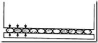
Figure 1: Clamped slivers between the nipper plates

Figure 2: Fibers
projecting from the nippers

Figure 3: Different types of fiber hooks
i.e. in this case the disposition of the hooks. As it is known over 50% of fibers in card sliver have trailing, 10% of leading type and 10% double hooks (Figure 3).
When the slivers are transferred from one stage of processing to another, a reversal in the hooks takes place as shown in figure 4. The combing process assists a great deal in straightening leading hooks. It is important, therefore to arrange the process preceding combing in such a way that the majority of hooks entering the combing process are leading type. The positioning of two processing stages (drawing and lap forming) between carding and combing fulfills this requirement.

Figure 4: Hooks reversal during processing
Another important criterion is the card sliver that has a direct impact on combing performance in sliver cohesiveness. The card sliver used in combing preparation should have a high level of cohesiveness. A suitable card sliver should have at least a 100 m breaking length. The combing process on the other hand produces a sliver that has poor cohesiveness due to the great deal of straightening and parallelization of fibers. Typically, a combed sliver has a cohesion level of less than 35m breaking length.
Methods of preparation:
Conventional (Lap Doubling) method:
Sliver Lap (D=16 ... 24, V=1.1 ....2) and Ribbon Lap (D=6, V=6)
In the conventional (sliver lap/ribbon lap) method a number of card slivers 16 to 32 are fed to a sliver lap machine, which consists of three pairs of drafting rolls followed by two pairs of calender rolls. A pair of lap varying in weight from 50 to 70 g/m, the lap width of about 230 to 300 mm (9.5 to 12 inch) and diameter of 500mm and weight of to 27Kg. Draft ratio commonly is 1.5 to 2.5.
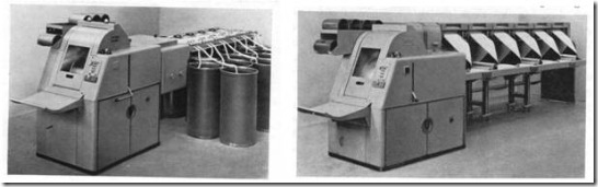
Figure 5: Sliver lap Machine Figure 6: Ribbon lap machine
Laps from the sliver lap machine are taken to the ribbon lap machine. Most ribbon lappers are four heads (earlier 6 heads), four independent sections, each of which process a single sliver lap. Accordingly four thin sheets of from the various heads are led down over a curved plate, which turns at a right angles, inverts them and superimpose one upon the others. The drafts used in the ribbon lapper are about four, so the weight per meter of the ribbon lap is about the same as that of the sliver lap.

Figure 7: The super lap machine of Whitin
About 20 drawing slivers are fed to a vertical 2/3 daft system, and drafted 3 to 5x. Three such unit are assembled in the machine. The laps are super imposed (width of 293 mm =11.5 inch) and through a pair of calander rolls, the batt is
compressed and the lap is formed.
Unilap from Rieter (drawing/lap)

Figure 8: Combing preparation (pre-drawing and lap forming
The sliver-lap/ribbon-lap is no longer used in modern mills except in situations where very fine yarns from extra long staple fibers are produced. The breaker drawing/lap-forming method is used for most combing preparation. This method is suitable for a wide range of fiber length from medium to long staple. It involves two steps: a standard drawing process in which a number of card slivers (typically 20 – 24) are drawn together to form a drawn sheet

Figure 9: Feed table
of slivers, and a lap winding process to form a lap weighing 50 – 70 g/m, which is ready to be combed (fig 8). Rieter uses heavier lap weights 65 to 80 Ktex, the delivery speed up to
100m/min. The production rate is up 360 kg/h. Laps of up to 25 Kg weight, 250-300 mm width and CV% evenness of 0.3% to 0.5% are produced. The Unilap system is designed to achieve fully automatic doffing and transportation of laps to the combing.
The Combing Machine:
The basic elements of the combing machine are shown in figure 10. These are the feeding element, the nipper plate, the combing system and the detaching rollers. The feeding element consists of a feed plate and feed roll. The main function of the feeding element is to feed the comber lap in a series of short lengths. The nipper plate grips the fibers as a means of holding long fibers while the short fibers, neps, and trash are being removed.
The combing system consists of two combs. The first one is a rotating bottom circular comb that performs the main combing action. The second one is a linear top comb that completes the function of the bottom comb through vertical combing movement.
The detaching rolls are two pairs of gripping rolls that rotate forward and backward in
intermittent fashion to hold and move the combed web for a net forward travel.
The objectives of combing
mentioned earlier are accomplished by a precise sequence and synchronized series of actions performed by the combing elements. The following text will review this sequence of actions, or the combing cycle, in a very simplified manner to demonstrate the function of each comber component.
The Combing Cycle:
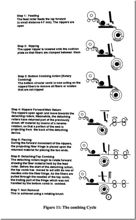
The following figures illustrate the different actions involved in the combing cycle. The principle of combing is to advance a pre-determined portion of the fiber lap to the combing station. This portion is then gripped by a pair of nipper plate while a toothed half (bottom comb) is combing the fiber fringe and removing the short fibers, neps and trashes. This waste (noil) is later removed from the needles of the bottom comb using a revolving brush. The detailed actions are illustrated in the figures:


The noil theory of Gegauff:
This noil theory was developed by Gegauff. Calculations made on the basis of the theory are often intractable and should be therefore not be attempted.
Symbols used in the following text have the following meanings;
Figure 12: Position of the nippers relative to the detaching cylinders at closest approach (detaching setting E) during counter feed.
Z: nippers; A: detaching rollers; B: Fiber fringe protruding from nippers; K: Combing segment; E: Detachment setting, i.e. distance between the bite of the nippers and the nip of the detaching rollers; S: Feed distance (mm) moved per combing cycle; M: longest fiber in the stable length (mm).
Two types of feeding are used in combing process:
Concurrent feed: implies feed of the sheet into the nippers occurs while the nippers are removed towards the detaching rols; (forward feed).
Counter-feed: implies feed of the sheet occurs during return of the nippers.
Figure 13: Combing out with counter feed (staple diagram)
The triangle areas represent stylized staple diagram; (backward feed).
Noil elimination with counter-feed (backward feed):
During the detaching step, the
nippers are located at their closest spacing relative to the detaching rollers, figure 12, which draw off all fibers extending to the nip line, i.e. all fibers longer than E. This length E can be
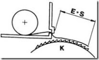
Figure 14: combing out the fiber fringe
entered in the staple diagram (figure 13) as a line m-n. All fibers to the left of the line m-n pass into the combed sliver (hatched area AmnC).
As the nipper retract towards the combs, the feed rollers shifts the fiber fringe forward through the feed distance S (figure 14) The fringe projecting from the nippers is now presented to the cylinder combs with the length E+S. All fibers shorter than E+S are carried away by the cylinder combs because they are not clamped. In the staple diagram, this length can be entered as line q-r. In this step, all fibers to the right of the line q-r are combed out into the noil (dotted are qBr).
In the region qmnr it is a matter of chance whether the fibers remain in the fringe or pass into the noil. Accordingly, a division can be made based on the mean fiber length represented within this area and it can be assumed that trapezium AcpC represents fibbers transferred to the combed sliver and triangle oBp represents those passing into the noil. The dividing line between these areas has the length E+S/2. Since in similar triangles the areas in the same ratio as the squares of the sides, and since the noil percentage is based on the ratio of waste to the weight of feedstock, the following relationship can be assumed:
p% = [(oBp) /(ABC)] * 100 = [(op)2 /(AC)2 ] * 100
{ [E + (S / 2)]2 /M2 } * 100
Noil elimination with concurrent feed:
After the detaching step has been completed, all fibers longer than E has been carried away. Science there is no feed step during the return stroke of the nippers, the fringe is presented to the cylinder combs with the length E. All fibers shorter than E pass into the noil; this is represented in the staple diagram in figure 16 by the area qBr. Feed occurs during the subsequent forward stroke of the nippers during which the fringe is increased in length by the distance S. Fibers longer than (E-S) are therefore carried away into the combed sliver and the trapezium Amnc represents these fibers.
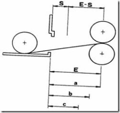
Figure 15: Position of the nippers relative to the detaching cylinders at the closest approach during concurrent feed.

Figure 16: Combing out with concurrent feed (staple diagram)
In this case also, the figure qmnr can be divided according to mean fiber length by the line o-p (E-S/2), and thus the following relationship can be derived:
p% = [(oBp)/(ABC)]*100
= [(op)2 /(AC )2 ] * 100
={[E−(S/2)]2/M2 }*100
From the two derived relations, it follows that where counter feed is used, noil is increased as the feed distance is raised, whereas in concurrent feeding, noil reduced as feed distance is increased.
THE TECHNOLOGY OF COMBING:
Parameters influencing the combing operation:
Raw material: Fiber type; fiber length; uniformity of fiber length (cv); fiber stiffness; moisture content.
Material preparation: Parallelization of fibers in sheet; sheet thickness; sheet evenness; orientation of hooks.
Factors associated with machine:
Condition of machine; condition of combs; speeds; operation of combs; type of piecing; accuracy of setting; drafting arrangement.
Machine setting:
Feed distance; type of feed; detachment setting; point density of combs; piecing; draft and draft arrangement settings.
Ambient conditions:
Room temperature, humidity
Influence of feed stock on combing:
Parallelization of fibers in the sheet:
➢ Lake of longitudinal orientation, i.e. noticeable fiber disorder, leads to elimination of longer fibers, and hence overloading the cylindrical comb (Thick sheet).
➢ At same machine settings, noil quantity decreases linearly with increasing
parallelization of the fibers without any reduction in yarn quality (see figure 17.)
➢ It is not always follow that more noil is automatically associated with better yarn
quality. The correct goal is always a predetermined waste elimination level.

Figure 17: Dependence of noil elimination on degree of parallelization (draft) of
fibers in the feedstock. A: Noil percentage. B: draft between card and comber.
➢ The self cleaning effect of the sheet, will be greater the more random is the disposition of the fibers making up the sheet. If the fibers have a very high degree of parallelization, the retaining power of the sheet can be so strongly reduced that it is no longer also able to hold back the neps as it usually does. Some of the sheet neps also pass through the top comb. Neppiness of the web is increased.
➢ If the degree of order of fibers is too high, the sheet does not hold together well. ➢ High degree of parallelization always leads to marked hairiness of the lap.
➢ The degree of parallelization depends on the total draft between the card and the
comber (see figure 18)
Figure 17: Yarn strength and cleanliness versus the degree of parallelization
A improvement or deterioration in %, B draft between card and comber
Sheet thickness:
➢ A thick sheet always exerts a greater retaining power than a thin one.
➢ Also, a thick sheet always applies
a strong load on the comb and this can lead to uncontrolled combing.
➢ In case of very thick sheet, the
fibers farthest from the cylinder comb may escape the combing operation, because the combs are no longer able to pass through the whole layer.
➢ Optimal sheet fineness now normally lies between 55 and 75 ktex. Typical values can be derived from figure 8.


Figure 18: Typical values for the fineness of the feed sheet. A: sheet fineness and B: Staple length; I, Comber from previous generation; II combers from current generation.
Evenness of the lap sheet:
➢ Evening of the lap is of considerable significance “better clamping”. ➢ High degree of evenness is due to higher doubling.
➢ This explains the effect of doubling on the ribbon lab machine.
The disposition of the hooks:
➢ Fibers should be presented to the comber so that leading hooks predominate in the feedstock.
➢ If the sheet is fed in the wrong direction, the number of neps rises markedly.
➢ Quantity and form of fiber hooks depend mainly upon the stiffness of the fibers; this
rises to the second or third power with increasing the coarseness of the fibers.
➢ Fine and long fibers, will always exhibit more and longer hooks (horseshoe shape)
than short fibers, coarse fibers (hokey stick form).
➢ Accordingly the role of fiber hooks in spinning process becomes more significant as fibers become finer.
Influence of combing operation on quality:
Combing can be applied to a wide range of spinning processes. Following is the classification of quality of combed yarns:
➢ Semi-combed (upgrading to higher grade) with noil percentage of 5 -10% (-12%)
➢ Normally combed, with a noil percentage
between 10 and 20 %.
➢ Super combed, with noil percentage over 20%.
Figure 19: Staple diagram a) before Combing; b) after combing; c) noil


Figure 20: Dependence of various quality parameters
on noil. A, improvement of yarn quality %; B, Noil
In %; a) yarn strength, b) yarn evenness; )
yarn Imperfections.
Read more...
➢ Elimination of precisely pre-determined quantity of short fibers;
➢ Elimination of the remaining impurities;
➢ Elimination of a large proportion (not all) of the neps in the fiber material; ➢ Formation of a sliver having maximum possible evenness;
➢ .Producing of more straight and parallel fibers.
Elimination of short fibers produces an improvement mainly in staple length, but also affects the fineness of the raw material. The micronaire value of combed sliver is slightly higher than that of feedstock (elimination of dead fibers). Also the degree of parallelization might reduce the inter-fiber adhesion in the sliver to such an extent that fibers slide apart while being pulled out of the can – i.e. sliver breaks or false drafts might be caused.
Types of applications:
The amount of material combed out varies within the range 5 – 25% of the in feed stock. Three major groups of spinning mills using combing are as follows:
➢ Long staple combing mills; Processing first-class, expensive cotton of high strength, containing a low proportion of short fibers and little dirt. The product is a fine to very fine yarn of top quality. The demands placed on know-how and skill of operating personnel is correspondingly high, as they are on the design and maintenance of the machines. Yarn production is low, while generation of noil is high.
➢ Medium-staple combing mills; here medium cotton qualities with a wide spread of quality parameters are spun to medium (to fine) yarns of good quality at economic production costs. The process is problematic in that it has to achieve a high strand of quality and at the same time give high production at low cost. The maximum demands placed on medium staple combing can only be fulfilled by optimally trained personnel.
➢ Short (to medium) staple combing mills; raw material used have the same as that for production of carded yarns. In comparison with a carded yarn, the combed yarn should chiefly exhibit better smoothness and strength. In this combination with low level noil level (6 – 14%). This process is the most widely used in practice; it is technologically undemanding and can be operated without problems when good machines are available.
Types of comber:
The major types of combers include:
➢ Rectilinear comber (with stationary or oscillating nippers), ➢ Circular combers (English worsted process),
➢ Rotary comber (production of Schappe spun yarns) and ➢ Hackling machines (bast fibers).
The short staple spinning mill uses only the rectilinear comber with swinging nippers and stationary detaching rollers, as originally developed in 1902 by the Englishman Nasmith and in 1948 by whitin company. Machine layouts used in practice comprise single sided machines with eight heads.
PREPERATION OF STOCK FOR COMBING:
The raw material delivered by the card is unsuitable for combing both as regards form and fiber arrangement. If card slivers were fed to the comber, then true nipping by the nipping plates would occur only on the high points, with the risk that the nippers could not retain the less strongly compressed edge zones of the slivers. These could then be pulled out as clumps by the cylinder combs. A sheet with greatest possible degree of evenness is therefore required as in feed to the comber.
A good parallel disposition of fibers within the sheet is a further prerequisite. If the fibers lie across the strand (a in fig. 1), even long fibers are presented to the cylinder combs as if they were short fibers (as shown in b) and they are eliminated as such. This represents unnecessary loss of good fibers.
The fiber arrangement must also be taken in consideration,
Figure 1: Clamped slivers between the nipper plates
Figure 2: Fibers
projecting from the nippers
Figure 3: Different types of fiber hooks
i.e. in this case the disposition of the hooks. As it is known over 50% of fibers in card sliver have trailing, 10% of leading type and 10% double hooks (Figure 3).
When the slivers are transferred from one stage of processing to another, a reversal in the hooks takes place as shown in figure 4. The combing process assists a great deal in straightening leading hooks. It is important, therefore to arrange the process preceding combing in such a way that the majority of hooks entering the combing process are leading type. The positioning of two processing stages (drawing and lap forming) between carding and combing fulfills this requirement.
Figure 4: Hooks reversal during processing
Another important criterion is the card sliver that has a direct impact on combing performance in sliver cohesiveness. The card sliver used in combing preparation should have a high level of cohesiveness. A suitable card sliver should have at least a 100 m breaking length. The combing process on the other hand produces a sliver that has poor cohesiveness due to the great deal of straightening and parallelization of fibers. Typically, a combed sliver has a cohesion level of less than 35m breaking length.
Methods of preparation:
Conventional (Lap Doubling) method:
Sliver Lap (D=16 ... 24, V=1.1 ....2) and Ribbon Lap (D=6, V=6)
In the conventional (sliver lap/ribbon lap) method a number of card slivers 16 to 32 are fed to a sliver lap machine, which consists of three pairs of drafting rolls followed by two pairs of calender rolls. A pair of lap varying in weight from 50 to 70 g/m, the lap width of about 230 to 300 mm (9.5 to 12 inch) and diameter of 500mm and weight of to 27Kg. Draft ratio commonly is 1.5 to 2.5.
Figure 5: Sliver lap Machine Figure 6: Ribbon lap machine
Laps from the sliver lap machine are taken to the ribbon lap machine. Most ribbon lappers are four heads (earlier 6 heads), four independent sections, each of which process a single sliver lap. Accordingly four thin sheets of from the various heads are led down over a curved plate, which turns at a right angles, inverts them and superimpose one upon the others. The drafts used in the ribbon lapper are about four, so the weight per meter of the ribbon lap is about the same as that of the sliver lap.
Figure 7: The super lap machine of Whitin
| (Sliver Doubling): e.g. Super lap from | |||
| Whitin: | |||
| Drawing | (D=8 ... | 10); V=6 | ... 8) |
| Super lap | (D=60; | V=3.5 .... | 4.5) |
compressed and the lap is formed.
Unilap from Rieter (drawing/lap)
Figure 8: Combing preparation (pre-drawing and lap forming
The sliver-lap/ribbon-lap is no longer used in modern mills except in situations where very fine yarns from extra long staple fibers are produced. The breaker drawing/lap-forming method is used for most combing preparation. This method is suitable for a wide range of fiber length from medium to long staple. It involves two steps: a standard drawing process in which a number of card slivers (typically 20 – 24) are drawn together to form a drawn sheet
Figure 9: Feed table
of slivers, and a lap winding process to form a lap weighing 50 – 70 g/m, which is ready to be combed (fig 8). Rieter uses heavier lap weights 65 to 80 Ktex, the delivery speed up to
100m/min. The production rate is up 360 kg/h. Laps of up to 25 Kg weight, 250-300 mm width and CV% evenness of 0.3% to 0.5% are produced. The Unilap system is designed to achieve fully automatic doffing and transportation of laps to the combing.
The Combing Machine:
The basic elements of the combing machine are shown in figure 10. These are the feeding element, the nipper plate, the combing system and the detaching rollers. The feeding element consists of a feed plate and feed roll. The main function of the feeding element is to feed the comber lap in a series of short lengths. The nipper plate grips the fibers as a means of holding long fibers while the short fibers, neps, and trash are being removed.
The combing system consists of two combs. The first one is a rotating bottom circular comb that performs the main combing action. The second one is a linear top comb that completes the function of the bottom comb through vertical combing movement.
The detaching rolls are two pairs of gripping rolls that rotate forward and backward in
intermittent fashion to hold and move the combed web for a net forward travel.
The objectives of combing
mentioned earlier are accomplished by a precise sequence and synchronized series of actions performed by the combing elements. The following text will review this sequence of actions, or the combing cycle, in a very simplified manner to demonstrate the function of each comber component.
The Combing Cycle:
The following figures illustrate the different actions involved in the combing cycle. The principle of combing is to advance a pre-determined portion of the fiber lap to the combing station. This portion is then gripped by a pair of nipper plate while a toothed half (bottom comb) is combing the fiber fringe and removing the short fibers, neps and trashes. This waste (noil) is later removed from the needles of the bottom comb using a revolving brush. The detailed actions are illustrated in the figures:
The noil theory of Gegauff:
This noil theory was developed by Gegauff. Calculations made on the basis of the theory are often intractable and should be therefore not be attempted.
Symbols used in the following text have the following meanings;
Figure 12: Position of the nippers relative to the detaching cylinders at closest approach (detaching setting E) during counter feed.
Z: nippers; A: detaching rollers; B: Fiber fringe protruding from nippers; K: Combing segment; E: Detachment setting, i.e. distance between the bite of the nippers and the nip of the detaching rollers; S: Feed distance (mm) moved per combing cycle; M: longest fiber in the stable length (mm).
Two types of feeding are used in combing process:
Concurrent feed: implies feed of the sheet into the nippers occurs while the nippers are removed towards the detaching rols; (forward feed).
Counter-feed: implies feed of the sheet occurs during return of the nippers.
Figure 13: Combing out with counter feed (staple diagram)
The triangle areas represent stylized staple diagram; (backward feed).
Noil elimination with counter-feed (backward feed):
During the detaching step, the
nippers are located at their closest spacing relative to the detaching rollers, figure 12, which draw off all fibers extending to the nip line, i.e. all fibers longer than E. This length E can be
Figure 14: combing out the fiber fringe
entered in the staple diagram (figure 13) as a line m-n. All fibers to the left of the line m-n pass into the combed sliver (hatched area AmnC).
As the nipper retract towards the combs, the feed rollers shifts the fiber fringe forward through the feed distance S (figure 14) The fringe projecting from the nippers is now presented to the cylinder combs with the length E+S. All fibers shorter than E+S are carried away by the cylinder combs because they are not clamped. In the staple diagram, this length can be entered as line q-r. In this step, all fibers to the right of the line q-r are combed out into the noil (dotted are qBr).
In the region qmnr it is a matter of chance whether the fibers remain in the fringe or pass into the noil. Accordingly, a division can be made based on the mean fiber length represented within this area and it can be assumed that trapezium AcpC represents fibbers transferred to the combed sliver and triangle oBp represents those passing into the noil. The dividing line between these areas has the length E+S/2. Since in similar triangles the areas in the same ratio as the squares of the sides, and since the noil percentage is based on the ratio of waste to the weight of feedstock, the following relationship can be assumed:
p% = [(oBp) /(ABC)] * 100 = [(op)2 /(AC)2 ] * 100
{ [E + (S / 2)]2 /M2 } * 100
Noil elimination with concurrent feed:
After the detaching step has been completed, all fibers longer than E has been carried away. Science there is no feed step during the return stroke of the nippers, the fringe is presented to the cylinder combs with the length E. All fibers shorter than E pass into the noil; this is represented in the staple diagram in figure 16 by the area qBr. Feed occurs during the subsequent forward stroke of the nippers during which the fringe is increased in length by the distance S. Fibers longer than (E-S) are therefore carried away into the combed sliver and the trapezium Amnc represents these fibers.
Figure 15: Position of the nippers relative to the detaching cylinders at the closest approach during concurrent feed.
Figure 16: Combing out with concurrent feed (staple diagram)
In this case also, the figure qmnr can be divided according to mean fiber length by the line o-p (E-S/2), and thus the following relationship can be derived:
p% = [(oBp)/(ABC)]*100
= [(op)2 /(AC )2 ] * 100
={[E−(S/2)]2/M2 }*100
From the two derived relations, it follows that where counter feed is used, noil is increased as the feed distance is raised, whereas in concurrent feeding, noil reduced as feed distance is increased.
THE TECHNOLOGY OF COMBING:
Parameters influencing the combing operation:
Raw material: Fiber type; fiber length; uniformity of fiber length (cv); fiber stiffness; moisture content.
Material preparation: Parallelization of fibers in sheet; sheet thickness; sheet evenness; orientation of hooks.
Factors associated with machine:
Condition of machine; condition of combs; speeds; operation of combs; type of piecing; accuracy of setting; drafting arrangement.
Machine setting:
Feed distance; type of feed; detachment setting; point density of combs; piecing; draft and draft arrangement settings.
Ambient conditions:
Room temperature, humidity
Influence of feed stock on combing:
Parallelization of fibers in the sheet:
➢ Lake of longitudinal orientation, i.e. noticeable fiber disorder, leads to elimination of longer fibers, and hence overloading the cylindrical comb (Thick sheet).
➢ At same machine settings, noil quantity decreases linearly with increasing
parallelization of the fibers without any reduction in yarn quality (see figure 17.)
➢ It is not always follow that more noil is automatically associated with better yarn
quality. The correct goal is always a predetermined waste elimination level.
Figure 17: Dependence of noil elimination on degree of parallelization (draft) of
fibers in the feedstock. A: Noil percentage. B: draft between card and comber.
➢ The self cleaning effect of the sheet, will be greater the more random is the disposition of the fibers making up the sheet. If the fibers have a very high degree of parallelization, the retaining power of the sheet can be so strongly reduced that it is no longer also able to hold back the neps as it usually does. Some of the sheet neps also pass through the top comb. Neppiness of the web is increased.
➢ If the degree of order of fibers is too high, the sheet does not hold together well. ➢ High degree of parallelization always leads to marked hairiness of the lap.
➢ The degree of parallelization depends on the total draft between the card and the
comber (see figure 18)
Figure 17: Yarn strength and cleanliness versus the degree of parallelization
A improvement or deterioration in %, B draft between card and comber
Sheet thickness:
➢ A thick sheet always exerts a greater retaining power than a thin one.
➢ Also, a thick sheet always applies
a strong load on the comb and this can lead to uncontrolled combing.
➢ In case of very thick sheet, the
fibers farthest from the cylinder comb may escape the combing operation, because the combs are no longer able to pass through the whole layer.
➢ Optimal sheet fineness now normally lies between 55 and 75 ktex. Typical values can be derived from figure 8.
Figure 18: Typical values for the fineness of the feed sheet. A: sheet fineness and B: Staple length; I, Comber from previous generation; II combers from current generation.
Evenness of the lap sheet:
➢ Evening of the lap is of considerable significance “better clamping”. ➢ High degree of evenness is due to higher doubling.
➢ This explains the effect of doubling on the ribbon lab machine.
The disposition of the hooks:
➢ Fibers should be presented to the comber so that leading hooks predominate in the feedstock.
➢ If the sheet is fed in the wrong direction, the number of neps rises markedly.
➢ Quantity and form of fiber hooks depend mainly upon the stiffness of the fibers; this
rises to the second or third power with increasing the coarseness of the fibers.
➢ Fine and long fibers, will always exhibit more and longer hooks (horseshoe shape)
than short fibers, coarse fibers (hokey stick form).
➢ Accordingly the role of fiber hooks in spinning process becomes more significant as fibers become finer.
Influence of combing operation on quality:
Combing can be applied to a wide range of spinning processes. Following is the classification of quality of combed yarns:
➢ Semi-combed (upgrading to higher grade) with noil percentage of 5 -10% (-12%)
➢ Normally combed, with a noil percentage
between 10 and 20 %.
➢ Super combed, with noil percentage over 20%.
Figure 19: Staple diagram a) before Combing; b) after combing; c) noil
Figure 20: Dependence of various quality parameters
on noil. A, improvement of yarn quality %; B, Noil
In %; a) yarn strength, b) yarn evenness; )
yarn Imperfections.


